
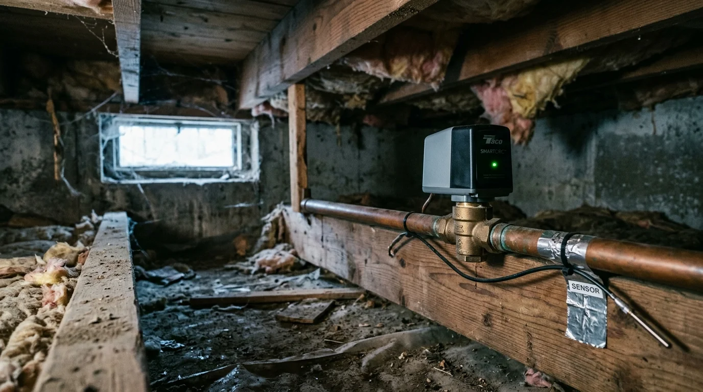
You can stop crawl space pipes from freezing during severe winter storms without wasting thousands of gallons of water or running continuous recirculation pumps. A dual-sensor predictive routine protects vulnerable plumbing by cycling an under-sink valve only when freezing conditions actively threaten your home.
For broader cold-weather protection during winter power or internet disruptions, establishing offline smart thermostat fail-safes provides a critical backup layer for vulnerable properties.
Standard freeze automations rely on blunt thermostat readings that either run pumps continuously or trigger too late. By pairing an ambient crawl space thermistor with an outdoor rate-of-fall temperature vector, you can eliminate freeze risk while slashing mechanical run-time by over 75 percent.
The Thermodynamics of Uninsulated Crawl Spaces
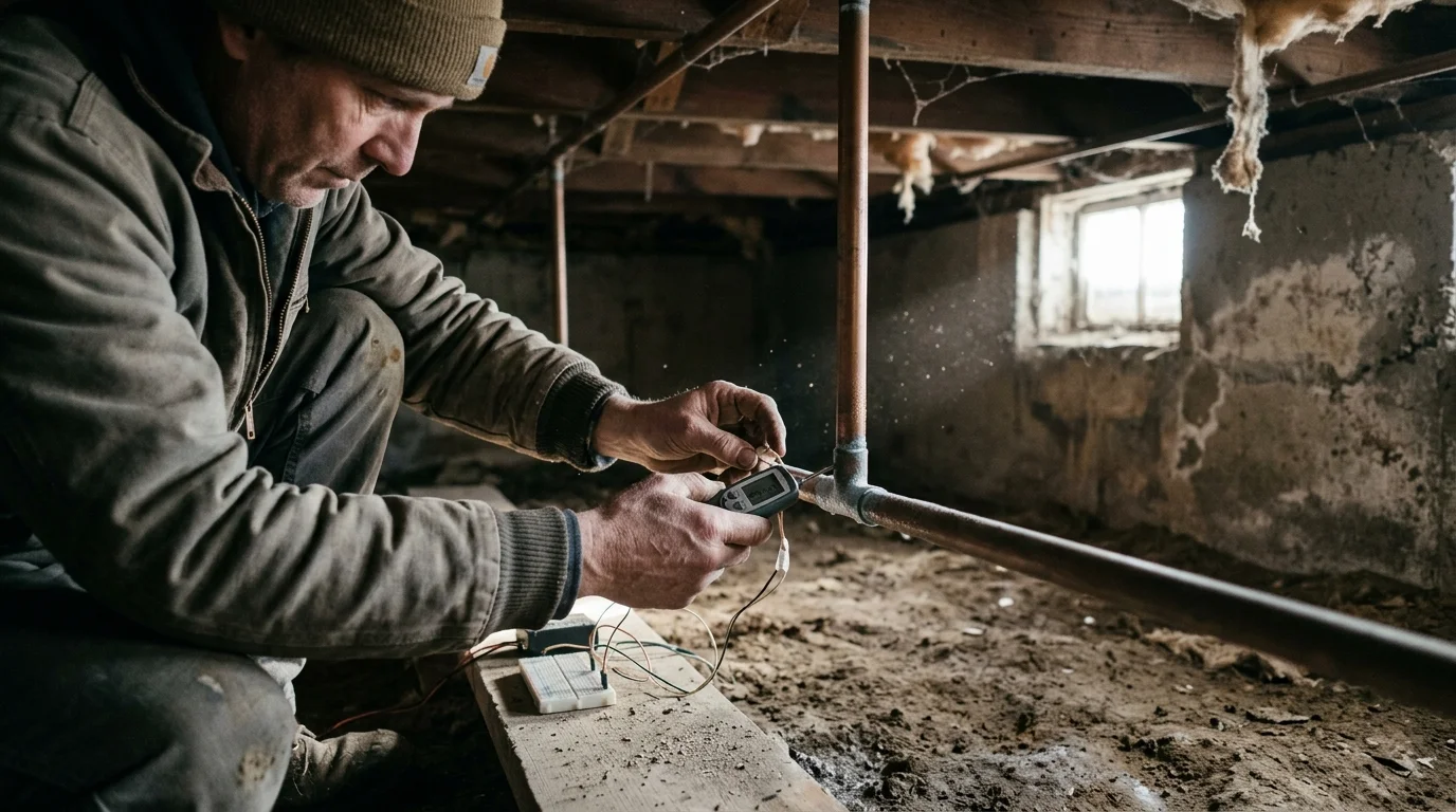
Uninsulated crawl spaces act as thermal sinks during cold snaps. Outside air infiltrates through foundation vents, creating localized wind tunnels that rapidly strip heat from exposed copper and PEX supply lines.
Much like protecting sensitive outdoor smart equipment with cold-weather enclosures and heaters during deep freezes, exposed plumbing networks require active thermal intervention.
Beyond burst pipes, homeowners face comparable moisture risks from drainage overflows, which can be mitigated by interlocking smart sump sensors with high-volume appliances.
Field research conducted by the Building Research Council at the University of Illinois established 20°F as the critical outdoor threshold. Below this temperature, uninsulated pipes in unconditioned spaces experience ice formation within hours.
Standing water in a residential pipe freezes from the pipe wall inward. As ice forms, it expands by roughly nine percent, creating hydraulic pressure downstream between the ice blockage and closed fixture valves.
This trapped pressure—not the ice volume at the freeze point itself—causes pipe bursts. The pressure frequently reaches thousands of pounds per square inch before the pipe wall ruptures.
The International Residential Code, under IRC Section P2603.5, mandates that water pipes shall not be installed in unconditioned crawl spaces unless protected by insulation, active heat, or both.
Insurance data reflects the severity of neglecting these zones. State Farm paid over $628 million across more than 20,000 frozen pipe claims between January 2024 and mid-2025.
The average claim payout exceeded $30,000 during that period. Additionally, the Insurance Information Institute reports that winter water damage affects roughly one in fifty insured homes each year.
Relying on traditional manual faucet dripping wastes clean domestic water and risks overflowing sinks if drains ice over. Smart valve recirculating freeze prevention solves this by recirculating warm water directly into the cold supply line.
Hardware Architecture for Smart Freeze Mitigation
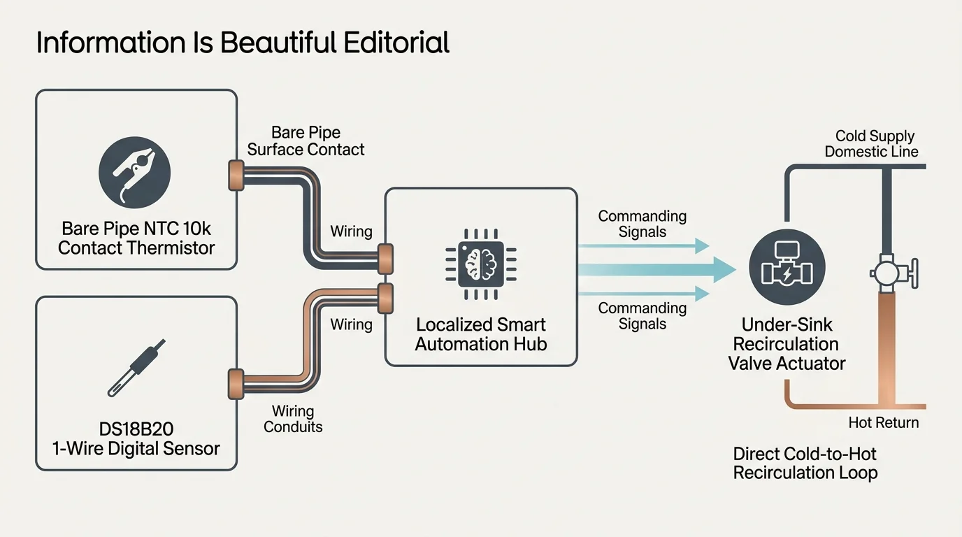
Automated crawl space freeze protection requires three connected components: temperature sensing probes, a localized smart automation hub, and an active recirculation mechanism.
If your setup includes supplemental line heaters, implementing power-drop auto-off automations adds an extra layer of electrical fire protection.
Similar to programming smart thermostat fan circulation cycles to redistribute air, moving warm water through stagnant supply lines eliminates severe temperature gradients.
Connecting your main shutoff valve and freeze sensors to a unified smart home emergency alert system ensures you receive push notifications or siren warnings if automated prevention fails.
For contact temperature readings, Negative Temperature Coefficient (NTC) thermistors or digital DS18B20 1-Wire sensors provide precise surface data. NTC 10k thermistors change electrical resistance predictably as temperature drops, providing immediate thermal feedback.
You must strap the contact sensor directly to the bare pipe surface. Placing an ambient sensor nearby is not enough because pipe material and water volume create thermal lag.
The second hardware tier consists of the smart controller. Platforms like Home Assistant, Hubitat Elevation, or Z-Wave relays handle sensor input and execute switching rules locally without depending on an active cloud connection.
Hardware testing guides from PCMag Smart Home emphasize that life-safety and flood-prevention automations should always operate on local hub hardware rather than remote cloud servers.
The mechanical tier uses either an under-sink thermal bypass valve or a dedicated recirculation pump. Systems like the Grundfos Comfort Valve or Taco Genie create a bridge between hot and cold lines at the furthest fixture.
To automate a standard thermal bypass setup, install a motorized smart ball valve on the bypass bridge. When open, hot water pushes through the cold supply pipe, elevating line temperatures above freezing.
Your hardware stack should include the following core components:
- One pipe-contact NTC thermistor or DS18B20 digital temperature probe with waterproof casing.
- One ambient crawl space temperature and humidity sensor with external antenna support.
- An outdoor weather station or local API temperature feed tracking barometric pressure and ambient temperature.
- A motorized under-sink cross-over valve or inline smart recirculation pump (such as a 120V smart relay controlling a Grundfos UP15-10B7).
- A high-torque smart main water shutoff valve on the primary home inlet as an emergency backstop.
Constructing the Dual-Sensor Predictive Logic
Single-sensor automations cause severe inefficiencies. If you trigger recirculation purely based on ambient crawl space air, your pump may run continuously for days during prolonged cold fronts.
Borrowing principles from deadband hysteresis configuration on smart relays prevents rapid contact cycling when pipe temperatures hover directly around threshold limits.
Much like configuring failsafe debounce logic for pump automation, implementing dwell timers prevents rapid oscillation caused by transient temperature fluctuations.
Conversely, triggering recirculation only when the pipe contact thermistor drops to 33°F leaves no margin for error. A rapid outdoor temperature plunge can freeze pipe elbows before warm water circulates.
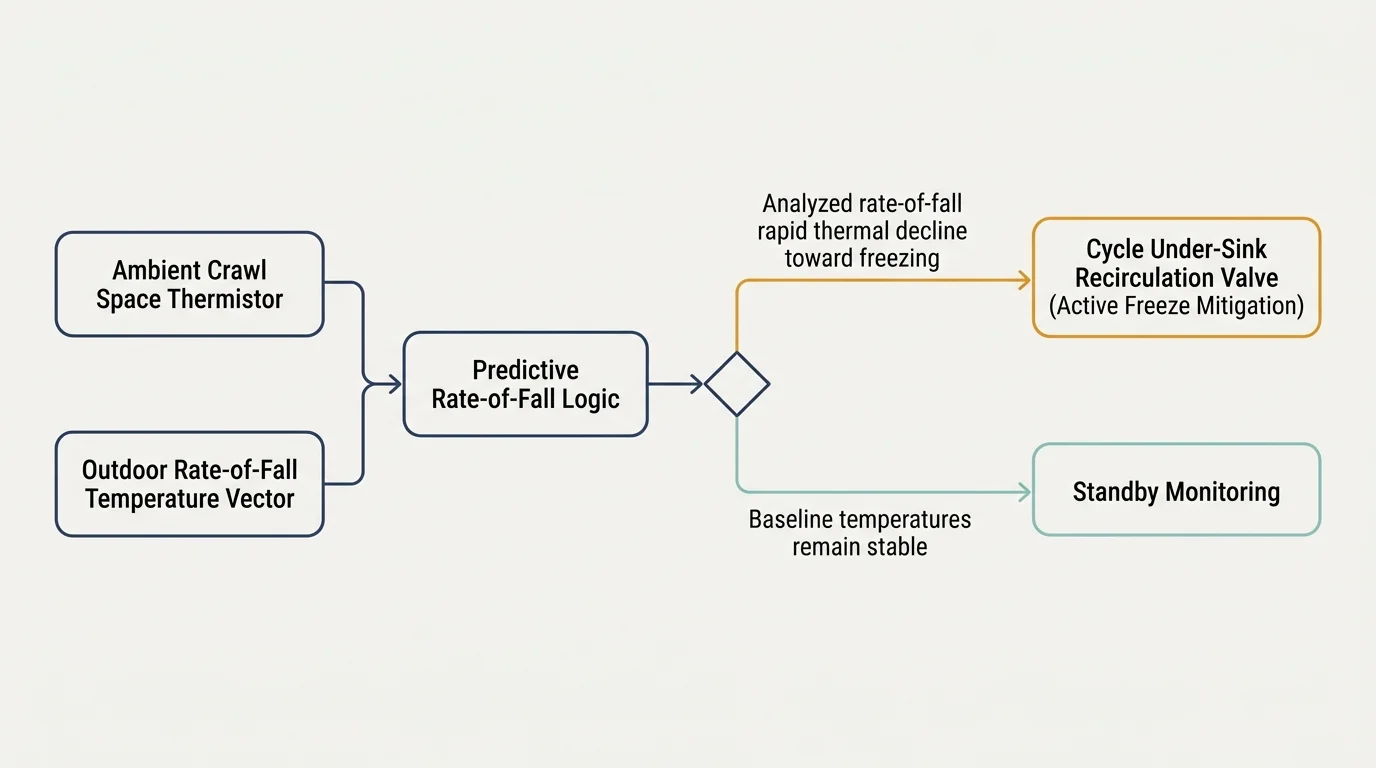
Dual-sensor predictive logic solves this through rate-of-change math. The automation monitors the internal pipe thermistor while simultaneously calculating the first derivative of the outdoor temperature decline.
Under this logic, the automation evaluates two primary parameters before actuating the bypass valve. It requires both an immediate thermal risk and an active cooling trend.
- Trigger Parameter A (Surface Temp): Pipe contact thermistor falls below 38°F (3.3°C).
- Trigger Parameter B (Crawl Space Temp): Ambient crawl space air temperature falls below 34°F (1.1°C).
- Trigger Parameter C (Trend Vector): Outdoor ambient temperature rate of change is less than or equal to -2.0°F per hour.
- Cycle Restriction: Valve actuates for a maximum run-time of 180 seconds, followed by a 15-minute dwell timer.
When Trigger Parameter A or B is true AND Parameter C is confirmed, the smart hub triggers the recirculation sequence. This predictive logic anticipates freezing hours before stagnant water reaches the nucleation threshold.
The short 180-second pulse pushes standing lukewarm water through the crawl space run, replacing it with 110°F water from the water heater. Thermal conductivity through the copper or PEX wall immediately stabilizes pipe temperature.
The system then enters a mandatory rest phase. This 15-minute dwell interval prevents the recirculation pump from over-cycling and stops hot water from filling the entire cold water plumbing distribution loop.
Step-by-Step Installation and Sensor Configuration
Deploying this smart pipe freeze protection system requires careful physical installation and clean automation rules. Complete each step in sequence to ensure reliable operation.
Because crawl spaces are damp and unconditioned, verify all auxiliary electronics and wiring meet robust weatherproofing standards, much like selecting sub-zero rated cold-start drivers for unheated outbuildings.
- Identify the furthest plumbing fixture: Locate the sink furthest from your water heater along the crawl space run. This fixture represents the end of the supply branch where stagnant water cools fastest.
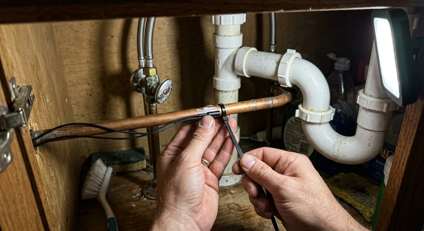
- Prepare the pipe surface: Scrape away surface oxidation or dust on a three-inch section of cold water pipe beneath the chosen sink. If using copper, ensure the metal shines clean to maximize thermal transfer.
- Mount the pipe thermistor: Apply a dime-sized amount of thermal heatsink paste to the sensor head. Fasten the thermistor securely to the bare pipe using metal hose clamps or heat-rated aluminum foil tape. Do not use plastic zip ties.
- Apply exterior pipe insulation: Wrap the thermistor and six inches of pipe on either side with closed-cell elastomeric foam pipe insulation. This prevents under-sink ambient air from corrupting your pipe contact readings.
- Install the under-sink bypass loop: Thread a smart motorized brass valve between the hot and cold angle stops under the sink using braided stainless-steel supply risers. Ensure valve directionality matches flow from hot to cold.
- Wire the smart actuator relay: Connect your motorized valve or recirculation pump to a dry-contact smart relay, such as a Zooz ZEN17 or Shelly Plus 1. Ensure the relay power supply connects to a GFCI-protected electrical outlet.
- Deploy the crawl space ambient sensor: Mount the secondary ambient sensor inside the crawl space, hanging roughly twelve inches below the floor joists near the most exposed foundation vent.
- Configure the hub routine: Input the dual-sensor logic into your smart hub, defining explicit trigger thresholds and lockout intervals to protect your pump motor.
Once wired, manually test valve actuation from your hub interface. Verify that the bypass valve opens completely within ten seconds and that hot supply water bleeds directly into the cold supply line.
Worked Example: Energy and Runtime Analysis
Consider an uninsulated 1,800-square-foot single-story home over an open, vented crawl space located in Climate Zone 5. The supply line consists of fifty linear feet of uninsulated 1/2-inch Type L copper pipe feeding an exterior-wall kitchen sink.
Just as calculating the economic balance point helps optimize dual-fuel systems, measuring the standby loss of hot water circulation ensures your freeze automation remains energy-efficient.
An arctic cold front moves through the region over a 48-hour period. Outdoor temperatures plunge from 33°F to 8°F, holding an average crawl space temperature of 24°F across two full days.
In a standard continuous-recirculation approach, a 25-watt recirculation pump (such as a Grundfos UP15-10B7) runs non-stop for 48 hours to maintain pipe warmth. This results in 1,200 watt-hours of electrical consumption.
More critically, continuous circulation continuously draws hot water out of the storage tank. The domestic water heater must burn an additional 72,000 BTUs of natural gas to counteract crawl space standby thermal losses.
Now evaluate the same 48-hour event using dual-sensor thermistor logic. The automation monitors pipe surface temperature alongside the rate of ambient drop.
The pipe thermistor drops to 37.8°F every 22 minutes. The hub verifies the outdoor drop rate (-2.4°F/hr) and triggers the bypass valve and pump for precisely 180 seconds.
Over the entire 48-hour freeze event, the smart valve cycles 104 times. Total cumulative pump operating time equals 312 minutes, or roughly 5.2 hours.
Total electrical consumption drops from 1,200 watt-hours down to 130 watt-hours. The water heater standby load decreases by 89 percent because hot water remains stationary until line temperatures drop near the safety threshold.
This targeted method completely prevented ice formation while eliminating unnecessary thermal stress on plumbing joints. It also prevented thermal creep from warming the domestic cold drinking water lines.
Hardware Comparison: Actuators, Valves, and Relays
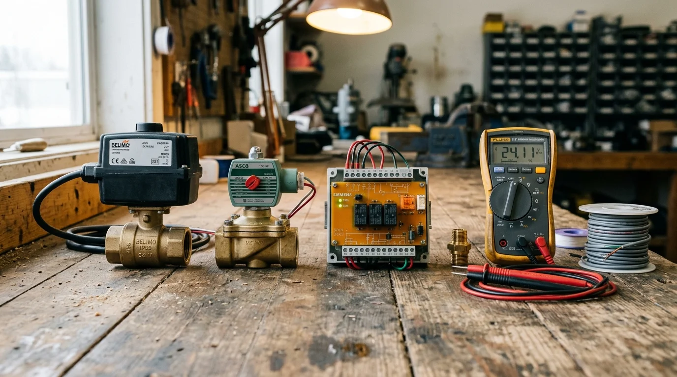
Selecting reliable equipment ensures your automation functions when grid conditions degrade. The table below compares hardware options for under-sink recirculation and smart valve actuation.
| Hardware Configuration | Protocol / Connectivity | Actuation Speed | Operating Wattage | Failsafe Mechanism | Hardware Cost |
|---|---|---|---|---|---|
| Motorized Brass Ball Valve + Zooz ZEN17 | Z-Wave Plus (800 Series) | 6 to 8 seconds | 5W (Active only) | Spring-return or NC wiring | $135 – $175 |
| Grundfos Comfort System + Smart Plug | Zigbee 3.0 / Wi-Fi | Instant (Pump start) | 25W (Continuous run) | Local thermal disc valve | $260 – $310 |
| Taco Genie 006-CT System | Hardwired / RF Relay | Instant (Pump start) | 50W (Active run) | Internal high-temp cutoff | $380 – $440 |
| YoLink Bulldog Smart Actuator | LoRa (Long Range) | 12 to 15 seconds | 8W (Active only) | Manual clutch lever | $170 – $210 |
Motorized brass ball valves wired to low-voltage smart relays provide the lowest steady-state power draw. They only consume electricity during the eight seconds required to open or close the ball orifice.
Dedicated recirculation pumps, such as the Taco Genie or Grundfos systems, move fluid volume much faster. However, their higher wattage demands careful duty-cycle management to prevent excessive energy bills.
Automation Failsafes and Network Redundancy
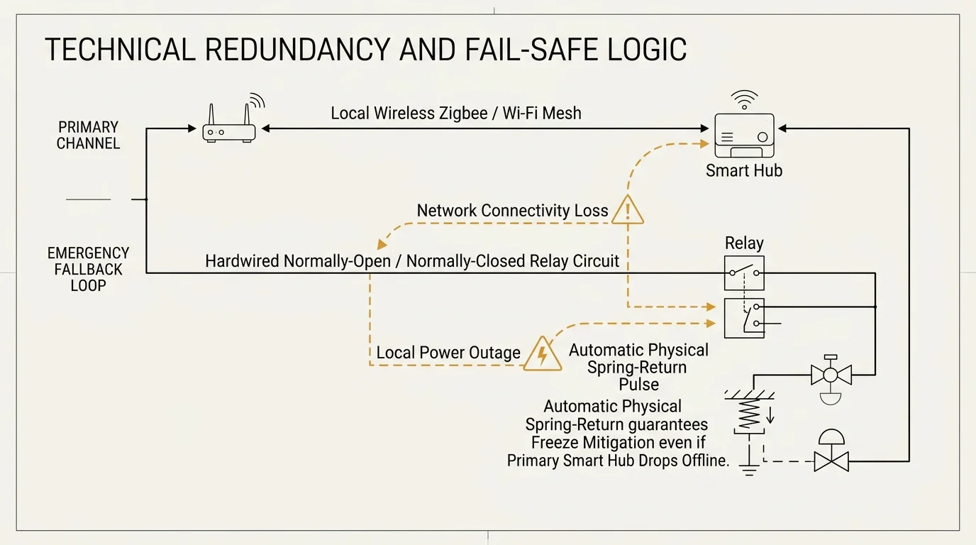
Smart automations must never fail into an unsafe state. A dropped Wi-Fi connection, frozen router, or dead sensor battery can disable a poorly planned automation loop.
Never rely exclusively on cloud platforms for freeze mitigation logic. Choose controllers using local wireless mesh standards or the Matter smart home standard to ensure commands execute across your local network without active internet service.
Implement heartbeat polling between your controller and the crawl space thermistor. If the hub does not receive a temperature payload within ten minutes, trigger an emergency fallback routine.
This fallback state should cycle the bypass valve for two minutes every twenty minutes automatically. This preserves freeze protection even if an individual sensor loses battery power or drops offline.
Protect your primary water inlet by integrating an automatic main shutoff valve into the same local network. If water pressure drops suddenly or a flow meter detects runaway consumption, shut the main valve instantly.
Hardware actuators like the Zooz Titan or YoLink Bulldog mount directly over existing quarter-turn ball valves. They include physical manual release clutches, allowing you to operate the valve by hand during a total electrical outage.
Review this redundant failsafe hierarchy when designing your system:
- Layer 1: Primary dual-sensor predictive automation running locally on the smart hub.
- Layer 2: Local hub fallback cycling triggered if thermistor heartbeat fails.
- Layer 3: Battery-backed smart main shutoff valve linked to an ultrasonic flow sensor.
- Layer 4: Mechanical thermal relief valve under the sink providing non-electric bypass operation.
Frequently Asked Questions
At what temperature will pipes freeze in an uninsulated crawl space?
Uninsulated pipes begin freezing when outdoor temperatures reach 20°F (-6.7°C) or lower for several consecutive hours. Drafty crawl space vents allow wind chill to freeze stagnant pipe water even when ambient outdoor air reads slightly above freezing.
Can I use PEX piping instead of copper to avoid freeze bursts?
While PEX expands slightly when water freezes, it remains vulnerable to failure at its mechanical fittings and crimp rings. PEX lines exposed to sub-freezing crawl space drafts still require active circulation or heat trace tape to prevent burst fittings.
How does an under-sink recirculation bypass valve work?
An under-sink bypass valve connects the cold and hot water supply lines beneath the sink furthest from your water heater. When opened, it uses the existing cold water line as a return path, pushing warm water through the cold line without discharging any water down the drain.
Will running this freeze routine make my cold tap water hot?
A properly tuned dual-sensor routine limits valve run-time to short two-to-three-minute pulses. This brief cycle warms the crawl space pipe run above freezing without flooding the entire cold distribution network with hot water.
Disclaimer: This article is for informational purposes only. Smart home devices involve electrical connections and data privacy. Always follow manufacturer instructions for installation. For complex wiring or HVAC work, consult a licensed professional.


1 Comment