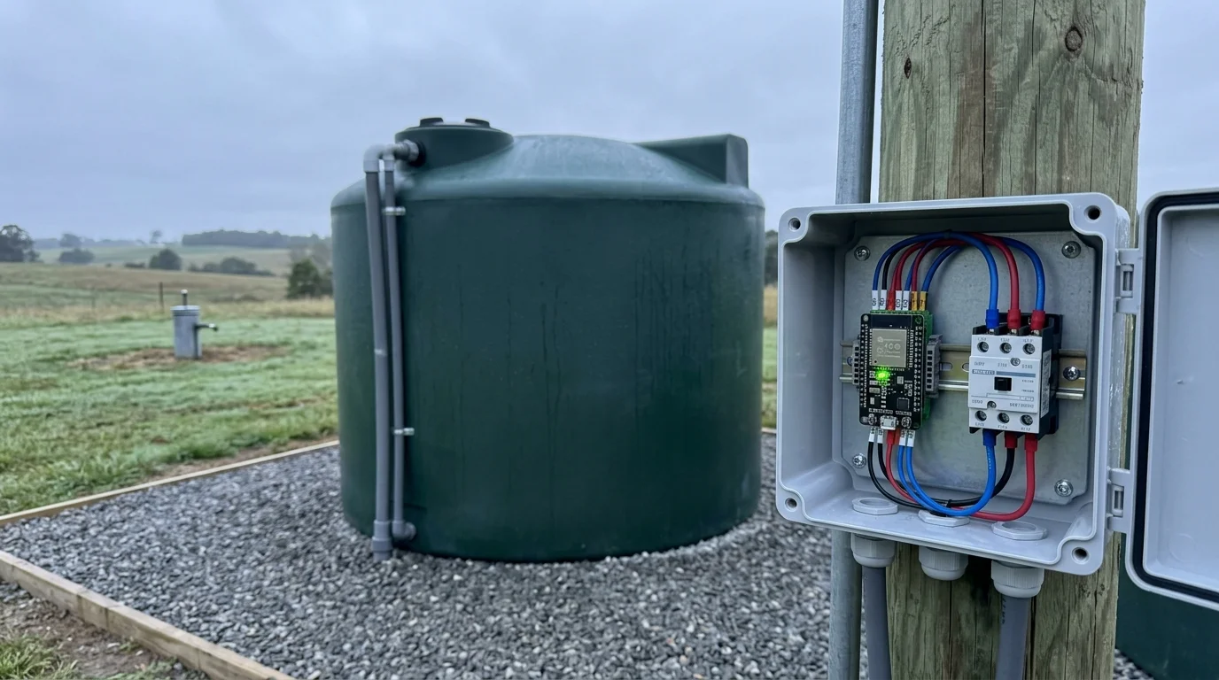
You can automate water replenishment between a slow-recharge well and a rainwater collection cistern without risking catastrophic pump burnout. A smart well pump controller routine balances dual-source water networks efficiently while safeguarding fragile aquifers.
Integrating dynamic storage triggers with broader weather-based smart home automations allows households to pause mechanical well transfers whenever significant rain storms approach.
Standard float switches and raw sensor automations fail because surface ripples cause rapid contactor chatter. Unlike typical tutorials that rely on instant triggers, this guide implements a mandatory 15-minute sensor debounce logic combined with strict pump runtime timeouts.
By decoupling sensor readings from direct motor switching, you eliminate short-cycling and protect your residential water supply during dry seasons.
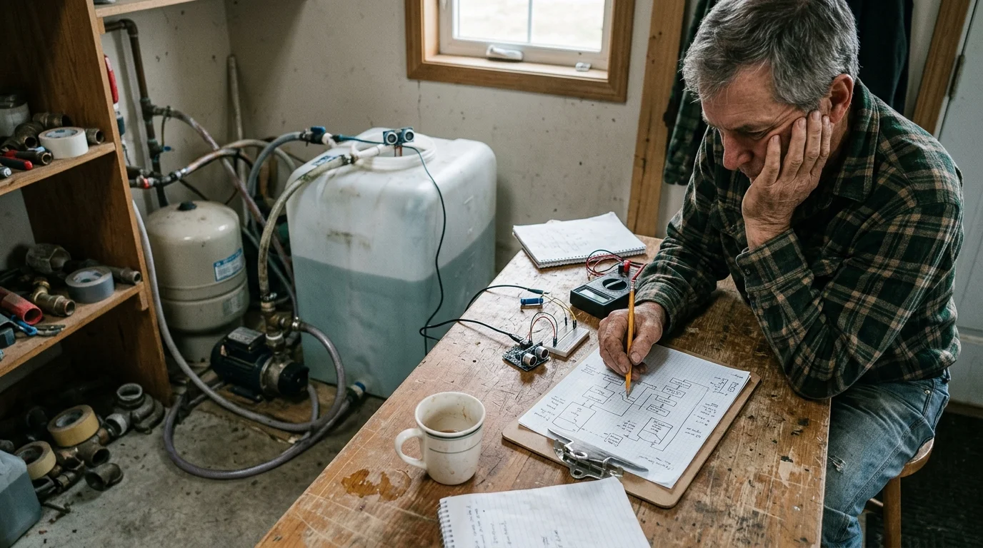
Dual-Source Hydrology: The Physics of Slow-Yield Wells
Rural homesteads often pair a rainwater harvesting cistern with a low-recovery residential well. This hybrid configuration shields your household from seasonal drought while reducing groundwater extraction.
Managing high-wattage inductive equipment like deep pumps is a key part of implementing energy-saving automations that lower your bills across rural properties.
Pairing cistern replenishment with barometric pressure pre-storm routines ensures your storage system pauses well transfers automatically ahead of incoming rain fronts.
Homesteaders frequently direct stored cistern water into automated garden watering systems to maintain irrigation schedules without placing continuous demand on fragile aquifers.
However, running a deep submersible well pump to top off a storage cistern introduces severe mechanical risks. If the pump draws down the water column faster than the aquifer recharges, air enters the intake impellers.
Submersible well motors rely on a steady flow of water across their exterior housing for thermal regulation. A pump running in air can overheat its motor windings within 90 seconds, causing irreversible insulation failure.
Furthermore, standard pressure-switch tanks provide no feedback regarding true cistern volume. Automating replenishment requires continuous depth tracking to avoid cycling the pump during transient household demands.
Hardware Architecture: Ultrasonic Sensors, Contactors, and Controllers
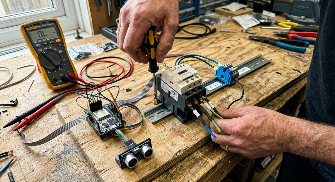
Automating deep-well pumping demands specialized hardware designed to handle electrical noise and damp environmental conditions. Consumer-grade smart plugs cannot withstand the inductive inrush currents of a 230-volt pump motor.
When packaging control electronics into compact enclosures, refer to smart relay installation and heat dissipation guidelines to avoid thermal throttling inside tight spaces.
For above-ground transfer lines exposed to harsh weather, implementing smart pipe freeze prevention with recirculation control protects your supply lines from catastrophic winter freeze damage.
Because deep-well pump motors demand significant inrush current during grid outages, consult a smart home power outage survival guide to ensure backup power supplies can support inductive motor loads.
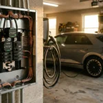
You must route pump power through a dedicated double-pole magnetic contactor rated for inductive motor loads. The smart controller switches the low-power 120-volt or 24-volt contactor coil rather than bearing the motor load directly.
For smart cistern water automation, pair an ESP32 microcontroller or industrial smart relay module with an outdoor-rated ultrasonic transducer. The A02YYUW or sealed JSN-SR04T sensor provides millimetric distance measurements while resisting saturated humidity inside sealed tanks.
As documented in automation hardware evaluations on PCMag’s smart home testing guides, local control protocols prevent cloud service outages from interrupting safety shutdowns. Always keep automation logic running on an on-premises hub.
- Ultrasonic Sensor: Sealed A02YYUW waterproof transducer with a 4.5-meter range and UART output.
- Controller Platform: ESP32 board flashed with local firmware or a dry-contact smart relay.
- Heavy-Duty Contactor: 2-pole, 30-amp definite purpose contactor with a 120-volt switching coil.
- Transient Suppression: RC snubber installed across coil terminals to quench inductive kickback spikes.
- Physical Disconnect: Manual three-position selector switch (Hand-Off-Auto) for emergency servicing.
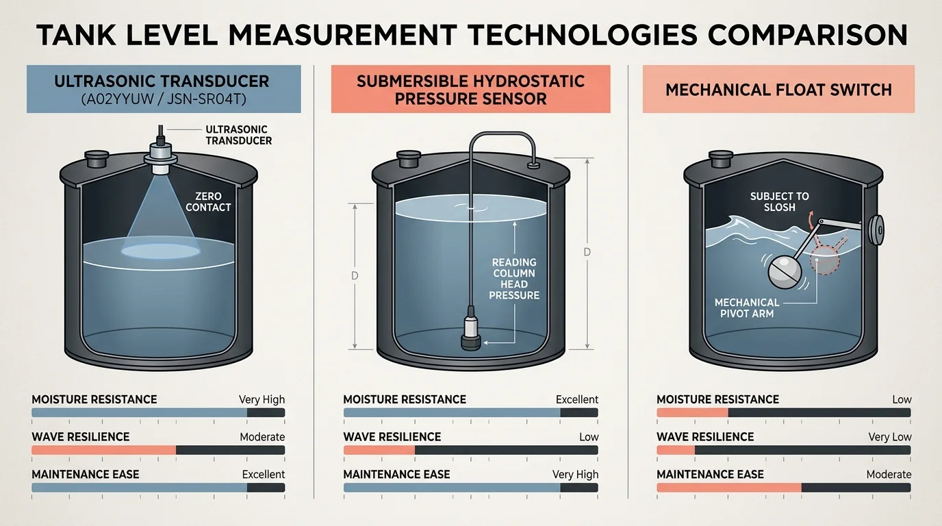
Sensor Technology Comparison: Ultrasonic vs. Hydrostatic vs. Floats
Selecting the correct sensing method dictates whether your automation loop operates reliably or fails due to environmental interference. Each technology handles water surface turbulence, chemical buildup, and vapor condensation differently.
Similar level-sensing safety interlocks are used when interlocking smart sump sensors with high-drain home appliances to protect household drainage systems from flooding.
Mechanical float switches remain popular due to low costs, but their moving parts invite mineral fouling and tether tangling. Submersible pressure transducers offer remarkable accuracy yet suffer from signal drift and probe corrosion over extended deployments.
Non-contact ultrasonic sensors eliminate submersion wear by measuring the acoustic time of flight from the cistern ceiling. They require a clear line of sight and must account for an acoustic blind zone near the transducer face.
| Metric | Waterproof Ultrasonic Sensor | Hydrostatic Pressure Probe | Mechanical Float Switch Array |
|---|---|---|---|
| Measurement Accuracy | ±1.0 millimeter resolution | ±0.5% full-scale depth | Binary step points only |
| Mechanical Wear Life | 100,000+ operating hours (solid-state) | 3 to 5 years (diaphragm fatigue) | 50,000 mechanical switch cycles |
| Media Exposure | Non-contact (vapor exposure only) | Direct water submersion (fouling prone) | Direct water submersion |
| Acoustic Deadband / Offset | 20 to 25 cm blind zone | Zero deadband (surface to bottom) | 5 to 10 cm switch hysteresis |
| Sensor Failure Mode | Echo loss (fails safe to zero fill) | Voltage offset drift (under/over fills) | Stuck contacts (runs pump indefinitely) |
Ultrasonic level sensing remains the superior choice for rainwater storage because it keeps sensitive electronics completely isolated from corrosive water chemistry. You only need to compensate for the sensor’s physical blind zone during installation.
Designing the 15-Minute Debounce and Hysteresis Logic
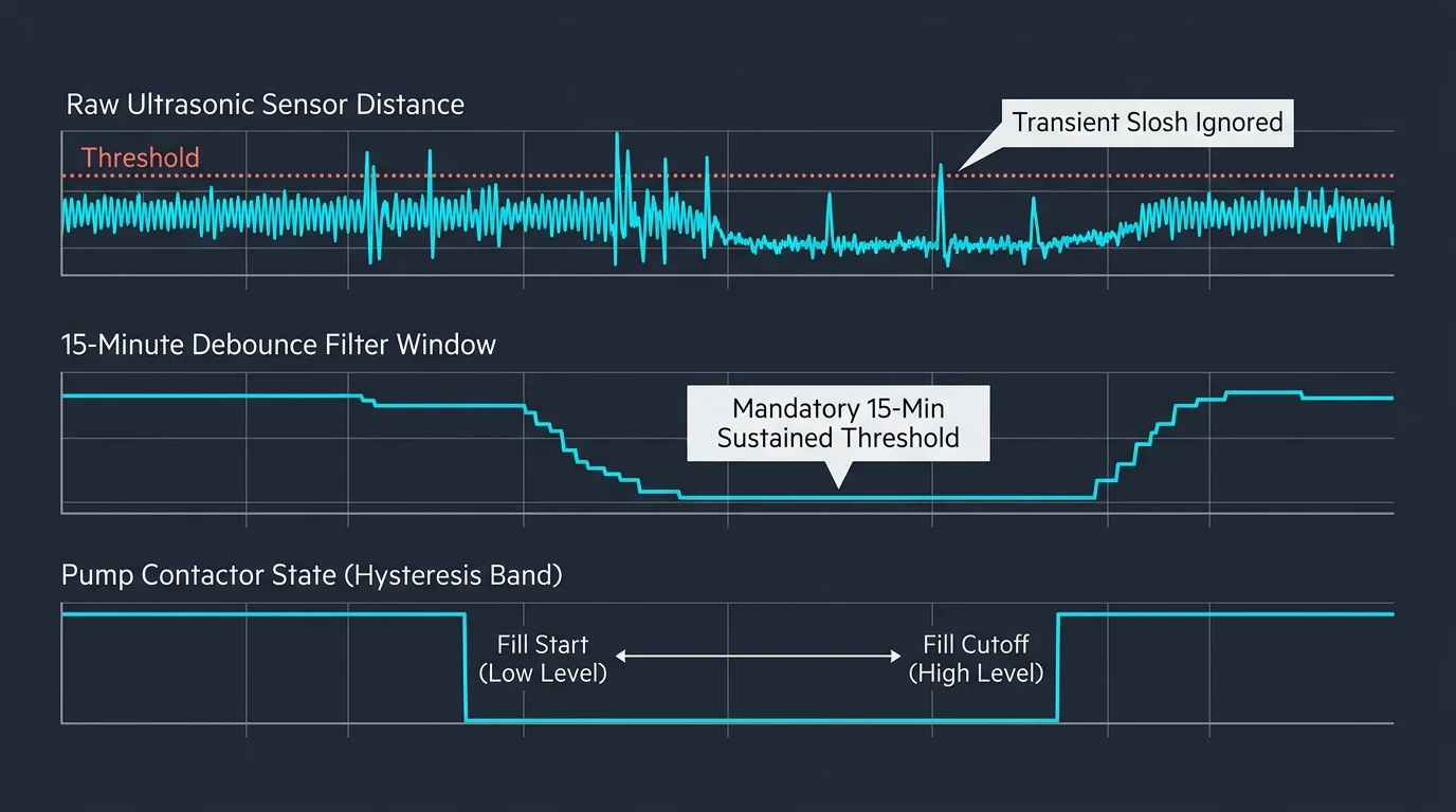
Water flowing into a cistern creates waves, ripples, and surface froth that distort raw ultrasonic distance readings. If your automation controller acts on momentary data points, small surface waves trigger rapid relay cycling.
Much like deploying offline thermostat fail-safes for freeze prevention, executing sensor debounce logic entirely on local hardware ensures pumps never miss a shutdown command due to network outages.
If water levels drop past critical minimum thresholds despite active pump logic, route urgent push notifications through a smart home emergency alert system to notify occupants immediately.
Rapid cycling—often called contactor chatter—arcs electrical contacts and severely damages motor capacitors. Establishing an ultrasonic tank sensor routine requires two distinct software filters: geometric hysteresis and temporal debouncing.
Hysteresis establishes wide separation between your start and stop thresholds. For instance, you might command the pump on at 35% tank capacity but prevent shutdown until the tank reaches 85% capacity.
Debouncing adds a time-verification delay to eliminate false readings from splashing water. The controller must observe continuous low-level measurements for 15 unbroken minutes before energizing the well pump contactor.
- Sample the ultrasonic distance every 15 seconds to generate an active telemetry stream.
- Apply a rolling median filter over 10 consecutive samples to strip out extreme acoustic outliers.
- Compare the median water depth against the predefined 35% cut-in threshold value.
- Start an internal 15-minute countdown timer once the median level crosses below the cut-in mark.
- Abort the countdown immediately if any median sample rises above the threshold during the timing window.
- Trigger the pump contactor relay only after the timer reaches zero with sustained low water levels.
Failsafe Dry-Run Protection: Timeouts and Power Sensing
A smart cistern routine cannot rely solely on tank level feedback to manage pump operation. A depleted well aquifer will starve the pump of water long before the cistern reaches its target shutoff level.
You can also synchronize pump transfer windows with scripted peak TOU load curtailment to avoid running high-draw well motors during expensive peak utility rate hours.
This approach relies on principles similar to power-drop auto-off automations, where sudden amperage reductions instantly trigger protective cutoffs.
To prevent catastrophic dry-running, your smart well pump controller routine must incorporate hard runtime cutoffs. If your well yields only 2 gallons per minute, the pump must never run continuously beyond a calculated safe window.
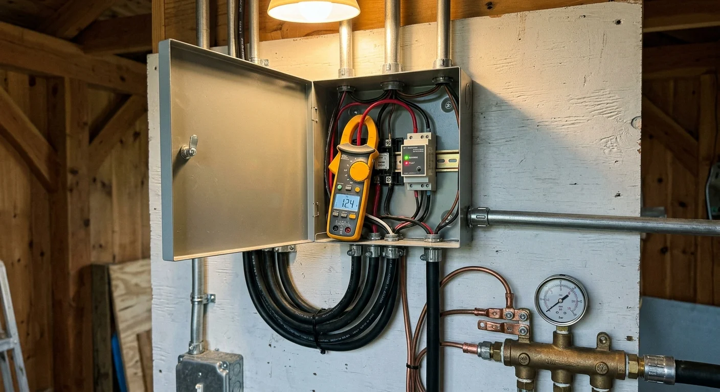
You can track power draw alongside runtime cutoffs using current monitoring relays, similar to setups highlighted in CNET’s connected home coverage. Electric motors draw significantly less amperage when spinning freely in air compared to pumping dense water.
A 230-volt, 0.5-horsepower submersible motor draws approximately 6.0 amps under full hydraulic load. When the well casing runs dry, that current draw plummets below 4.0 amps almost instantly.
- Maximum Run-Time Limit: Hard-code an absolute maximum pump duration of 30 to 45 minutes per cycle.
- Compulsory Well Recovery Dwell: Force a mandatory 90-minute lockout after every pumping cycle before re-evaluating tank levels.
- Current Threshold Monitoring: Shut down the motor if current drops below normal running load for more than 10 seconds.
- Daily Cycle Caps: Limit transfers to a maximum number of cycles every 24 hours to prevent aquifer over-drafting.

Step-by-Step Configuration: Programming the Transfer Routine
Setting up your automated transfer system requires careful sensor placement, safety interlocking, and robust logic structuring. Follow these sequential steps to commission your water transfer controller.
For installations in cold climates with exposed outdoor plumbing manifolds, pair your routine with smart pipe freeze prevention to keep above-ground transfer pipes clear of ice.
- Install the Standoff Collar: Mount the ultrasonic transducer inside an elevated PVC collar atop the cistern inspection port. Ensure the sensor face sits at least 30 centimeters above the maximum overflow line to avoid its acoustic blind zone.
- Wire the Motor Contactor: Connect your controller’s dry-contact relay in series with the magnetic contactor’s 120-volt coil. Never connect the main 230-volt pump motor power wires directly to micro-relays.
- Measure Tank Geometry: Record total tank height, maximum water level, and the physical distance between the sensor and empty tank floor. Convert raw distance readings into usable volume percentages in your controller software.
- Program the Debounce State Engine: Configure software variables requiring 60 consecutive consistent readings across 15 minutes before asserting the fill command.
- Set Up the Run-Time Watchdog: Establish a software watchdog timer that automatically unlatches the relay after 45 minutes, regardless of current sensor states.
- Implement Well Recovery Delays: Add an un-bypassable dwell timer that blocks subsequent motor activations for two hours after any transfer sequence completes.
- Conduct a Wet Dry-Run Test: Verify that disconnecting the sensor wiring during an active pumping event immediately opens the contactor circuit safely.

Worked Example: Sizing and Timing a 2,500-Gallon Homestead System
Consider a working homestead utilizing a 2,500-gallon vertical polyethylene rain cistern connected to a slow-recovery residential well. The household needs automated transfers that protect the slow well during seasonal summer droughts.
The cistern measures 96 inches in diameter and stands 84 inches tall. This geometry yields approximately 29.7 gallons of water storage per vertical inch of fluid depth.
The deep well drops 320 feet with a 6-inch casing. Static water rests at 180 feet, leaving a 140-foot standing column of water, equivalent to roughly 210 gallons of borehole storage reserve.
The continuous aquifer recovery rate measures 1.2 gallons per minute (GPM). The submersible pump delivers 5.0 GPM at standard household system pressure.
- Target Low Level (35% Capacity): 29.4 inches water depth (54.6 inches sensor distance). Triggers transfer logic.
- Target High Level (85% Capacity): 71.4 inches water depth (12.6 inches sensor distance). Terminates transfer logic.
- Pump Run Duration: Set strictly to 40 minutes per transfer cycle.
- Water Displaced per Cycle: 40 minutes × 5.0 GPM = 200 gallons pumped.
- Well Recovery During Cycle: 40 minutes × 1.2 GPM = 48 gallons recharged during active pumping.
- Net Borehole Drawdown: 200 gallons − 48 gallons = 152 gallons removed from standing casing storage.
- Borehole Safety Margin: 210 gallons reserve − 152 gallons drawdown = 58 gallons remain above pump intake at cycle completion.
- Required Well Recovery Dwell: 152 gallons ÷ 1.2 GPM = 126 minutes minimum rest before initiating subsequent pumping cycles.
Hardware costs for this protective automation remain remarkably affordable. The complete hardware setup costs $110.23, representing massive savings compared to a $2,800 deep-well pump replacement.
- A02YYUW Waterproof Ultrasonic Sensor: $18.50
- ESP32 Microcontroller Development Board: $8.99
- Packard C230A 2-Pole 30A 120V Contactor: $34.50
- IP65 Polycarbonate Enclosure and Glands: $22.00
- RC Snubber Arc Suppressor: $6.25
- 2-inch Schedule 40 PVC Standoff Fittings: $19.99
Troubleshooting Acoustic Echoes, Condensation, and Drift
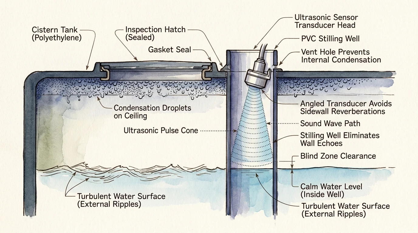
Even well-engineered automation loops encounter physical challenges inside rainwater tanks. Saturated relative humidity promotes condensation beads across the ultrasonic transducer face.
Condensation droplets distort acoustic pulses, causing the sensor to register phantom targets just inches from its face. Coating the transducer ring with a thin wipe of silicone fluid helps moisture bead and roll off naturally.
Acoustic reflections off internal structural ribs or inflow piping can also return premature false echoes. You can correct this by sleeving the ultrasonic sensor inside a vertical 4-inch perforated PVC stilling pipe that dampens surface turbulence.
Finally, inspect electrical contactor faces biannually for pitting or soot accumulation. Replacing pitted contactor points ensures the physical switch never welds shut, which would cause an uncontrolled cistern overflow.
Frequently Asked Questions
Why is a 15-minute debounce necessary for water tank sensors?
Water entering a cistern creates waves, bubbles, and splashing that distort instantaneous ultrasonic distance readings. A 15-minute verification window ensures the water level has genuinely dropped before starting the well pump.
Can I wire the well pump directly to a smart relay switch?
No, you must never connect a submersible well pump directly to micro-relays. Heavy motor startup currents will weld small relay contacts together, leading to pump burnout or severe fire hazards.
What happens if the ultrasonic sensor loses signal completely?
Your automation logic should treat an echo-loss signal as an immediate fault state. Configure your controller to unlatch the pump contactor instantly if sensor telemetry disconnects or returns out-of-range values.
How does temperature affect ultrasonic level accuracy?
The speed of sound in air shifts by approximately 0.6 meters per second per degree Celsius change. For precise liquid measurement across changing seasons, select an ultrasonic sensor module with built-in ambient temperature compensation.
Disclaimer: This article is for informational purposes only. Smart home devices involve electrical connections and data privacy. Always follow manufacturer instructions for installation. For complex wiring or HVAC work, consult a licensed professional.