
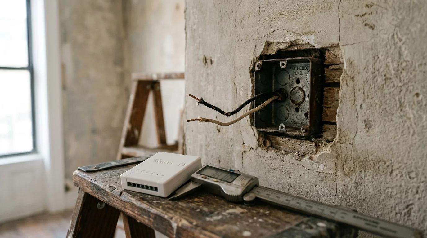
You can modernize your pre-war brownstone lighting without knocking down plaster walls or rewiring vintage switch boxes. Fitting a smart switch into a shallow 1.5-inch metal box requires calculating millimeter hardware depth alongside strict circuit capacitance.
While conventional advice insists you must wire a bulky bypass resistor inside your ceiling fixture canopy to stop LED micro-flickering, you can eliminate ghosting entirely by matching switches with sub-0.5 mA off-state leakage to native 25-watt capacitive loads.
This guide details the exact spatial clearances and electrical formulas required to safely install no-neutral switches in cramped vintage enclosures.
The Millimeter Challenge: Shallow Metal Boxes and NEC Fill Limits
Pre-war brownstones and historic urban apartments frequently feature shallow, single-gang metal junction boxes measuring just 1.5 inches deep. Builders installed these stamped steel or cast iron boxes decades before modern electronics existed.
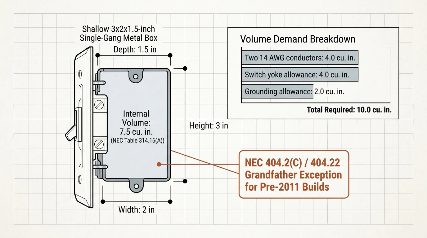
Under National Electrical Code (NEC) Table 314.16(A), a standard 3-by-2-by-1.5-inch device box yields an internal volume of merely 7.5 cubic inches. This compact volume creates severe restrictions when modernizing electrical devices.
Calculating box fill volume in accordance with NEC 314.16(B) illustrates the spatial dilemma. Every wire, clamp, and device claims a designated cubic-inch volume allowance inside the enclosure:
- Each 14 AWG hot and load conductor requires 2.00 cubic inches.
- Each 12 AWG conductor requires 2.25 cubic inches.
- A standard switch yoke claims two conductor volumes (4.00 cubic inches for 14 AWG, 4.50 cubic inches for 12 AWG).
- All grounding conductors collectively claim one conductor volume based on the largest ground wire (2.00 cubic inches for 14 AWG).
- Internal cable clamps claim one conductor volume collectively if present inside the box.
Summing these values reveals a significant challenge. Two 14 AWG conductors (4.0 cu. in.), a ground allowance (2.0 cu. in.), and a standard switch yoke (4.0 cu. in.) demand 10.0 cubic inches of volume.
Fitting 10.0 cubic inches of equipment into a 7.5-cubic-inch metal box technically exceeds standard fill tables. Fortunately, historical wiring methods often omit internal clamps, relying on external armor connectors.
Furthermore, NEC 404.2(C) and NEC 404.22 address this exact scenario with an explicit grandfathering exception. The code permits no-neutral replacement switches in pre-2011 installations where pulling a dedicated neutral conductor would require damaging finished plaster surfaces.
Managing this physical footprint requires picking hardware with the absolute shallowest chassis. Standard smart switches quickly bottom out against the steel backing plates, leaving no room for conductor bends.
Faraday Cage Physics: Why 2.4 GHz Fails in Pre-War Walls
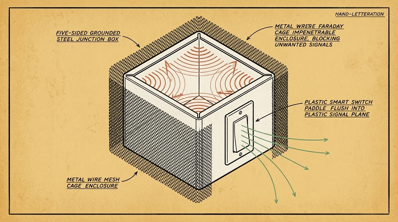
Grounded steel boxes create a functional Faraday cage that severely attenuates wireless communication. The metal enclosure shields radio transmissions on five of its six sides.
High-frequency 2.4 GHz wireless signals—including standard Wi-Fi, Thread, and Zigbee—struggle to escape these metal cavities. Their 12.5-centimeter wavelength cannot easily clear the narrow aperture around the switch faceplate.
Signal attenuation spikes higher when thick plaster and wire lath surround the metal box. The metal lath mesh acts as an extended radio barrier across the entire wall surface.
As documented in smart device testing by The Verge Smart Home, metal enclosures frequently cause dropped connections on standard 2.4 GHz networks. Signal packet loss increases whenever radios sit recessed behind dense metallic structural boundaries.
Proprietary sub-gigahertz wireless protocols offer an architectural advantage in pre-war construction. Lutron Clear Connect operates at 434 MHz, utilizing a radio wavelength of approximately 69 centimeters.
These longer radio waves diffract cleanly through the front opening of the wall plate. They travel around metallic barriers and penetrate dense masonry walls without severe signal degradation.
If you choose a 2.4 GHz Zigbee or Matter-over-Thread switch, you must place a mesh routing plug in direct line of sight of the switch faceplate. Doing so mitigates the high RF absorption caused by the steel box.

Switch Dimensions and Clearance: The 1.5-Inch Fit Test
Physical depth dictates whether your smart dimmer will mount flush against the wall surface. While traditional mechanical switches occupy less than 0.75 inches, smart switches carry internal power supplies and wireless radios.
In a 1.5-inch box, every millimeter of internal space counts. A switch body measuring 1.25 inches leaves only 0.25 inches (6.35 mm) of clearance behind the device.
That tiny quarter-inch gap must house stiff solid-copper wires and splicing connectors. Forcing a deep dimmer into the box risks pinching wire insulation or shearing connections.
The table below provides physical and electrical dimensions for the most reliable no-neutral smart dimmers suitable for shallow retrofits.
| Model & Protocol | Chassis Depth | Rear Clearance in 1.5″ Box | Standby Leakage Current | MSRP |
|---|---|---|---|---|
| Lutron Diva Smart Dimmer (DVRF-6L, 434 MHz) | 1.125 in (28.6 mm) | 0.375 in (9.5 mm) | 0.35 mA | $69.95 |
| Inovelli Blue Series 2-in-1 (VZM31-SN, Zigbee 3.0) | 1.200 in (30.5 mm) | 0.300 in (7.6 mm) | 0.45 mA | $55.00 |
| Leviton Decora Smart No-Neutral (DN6HD, Wi-Fi via Bridge) | 1.300 in (33.0 mm) | 0.200 in (5.1 mm) | 0.50 mA | $49.99 |
| Lutron Caséta Original Dimmer (PD-6WCL, 434 MHz) | 1.125 in (28.6 mm) | 0.375 in (9.5 mm) | 0.35 mA | $59.95 |
The Lutron Diva DVRF-6L offers the shallowest profile at 1.125 inches (28.6 mm) behind the mounting yoke. This compact design preserves 0.375 inches of critical rear wiring clearance.
Inovelli and Leviton models remain viable, but their deeper housings demand meticulous wire management. Every fraction of an inch saved prevents crushed conductors against sharp metal edges.
Preventing Micro-Flicker and Ghosting Without Ceiling Resistors
Two-wire smart switches must complete an electrical circuit to power their internal electronics. Without a dedicated neutral wire, the device draws a continuous standby trickle current through the connected lighting load.
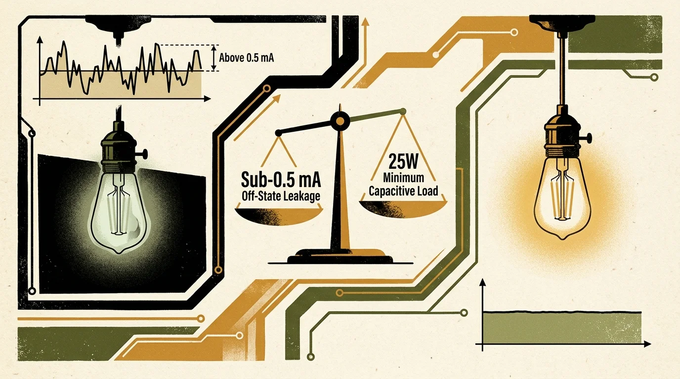
This off-state leakage current typically measures between 0.35 and 0.50 milliamperes. While traditional incandescent filaments absorb this tiny current without glowing, energy-efficient LED drivers behave very differently.
An LED driver contains internal input rectification capacitors. Standby trickle current slowly charges these capacitors until they reach the switching threshold of the internal power supply.
Once charged, the driver discharges energy through the LED emitters in a rapid pulse. This periodic discharge cycle creates the annoying phenomenon known as micro-flicker or ghosting.
Solid-state electronics require continuous potential; when deprived of a return path, the fixture itself becomes part of the device power supply.
Hardware manufacturers typically tell consumers to wire a bypass capacitor inside the ceiling fixture canopy. In rental brownstones with high lath-and-plaster ceilings, dismantling vintage chandeliers is often impractical or prohibited by lease agreements.
You can bypass the need for a ceiling-mounted capacitor by engineering the circuit’s native capacitive load. The switch requires a continuous minimum operating load to dissipate leakage without building voltage.
Maintaining a minimum total circuit load of 25 watts using high-power-factor (PF > 0.9) LED bulbs completely eliminates off-state flashing. Multi-bulb chandeliers distribute the leakage current across multiple parallel drivers.
Dividing a 0.35 mA standby leakage across five parallel bulbs drops the current per driver to just 0.07 mA. That tiny charge dissipates naturally across the driver bleeder resistors without ever initiating a flash cycle.

Step-by-Step Installation Protocol for Shallow Metal Enclosures
Installing a modern smart switch into an antique junction box requires careful mechanical planning. Follow this step-by-step protocol to achieve a clean fit without stripping insulation.
- Cut power to the lighting circuit at the main service panel, then verify the circuit is dead using a calibrated non-contact voltage tester.
- Unscrew the existing wall plate and extract the mechanical switch. Note the line and load wires using colored electrical tape.
- Inspect the interior of the metal box for burrs, protruding armor clamps, or degraded cloth-sheathed wiring.
- Wrap the cloth insulation near the conductor base with heat-shrink tubing or premium electrical tape if brittle.
- Verify chassis grounding. In BX-armored installations, confirm continuity between the metal box and the armored sheath using a digital multimeter.
- Replace bulky twist-on wire nuts with compact lever connectors, sliding conductors straight into the terminals.
- Fold the line and load conductors accordion-style into the bottom and top corners of the box cavity.
- Position the switch chassis into the center opening, ensuring no wires sit directly between the switch back and the rear steel wall.
- Secure the switch mounting yoke using shortened 6-32 machine screws to prevent bottoming out against the back of the box.
- Restore circuit power at the breaker panel and configure the switch’s low-end and high-end trim thresholds.
Using the right wire termination hardware makes a noticeable difference in tight enclosures. Consider these spatial optimization practices when dressing the junction box:
- Use Wago 221-412 compact splicing connectors instead of traditional twist nuts to cut termination volume by roughly 40 percent.
- Trim conductor leads to 5 inches; longer leads bunch up and consume irreplaceable depth.
- Tuck splicing connectors along the vertical edges of the box, keeping the central 1.2 inches clear.
- Use nylon washers on the mounting screws if the box sits recessed behind plaster, ensuring the yoke remains rigid.
Take your time seating the device into place. Never force the switch inward with power tools, which can easily crack internal circuit boards or shear aged conductors.

Worked Example: Living Room Chandelier in an 1890s Brownstone
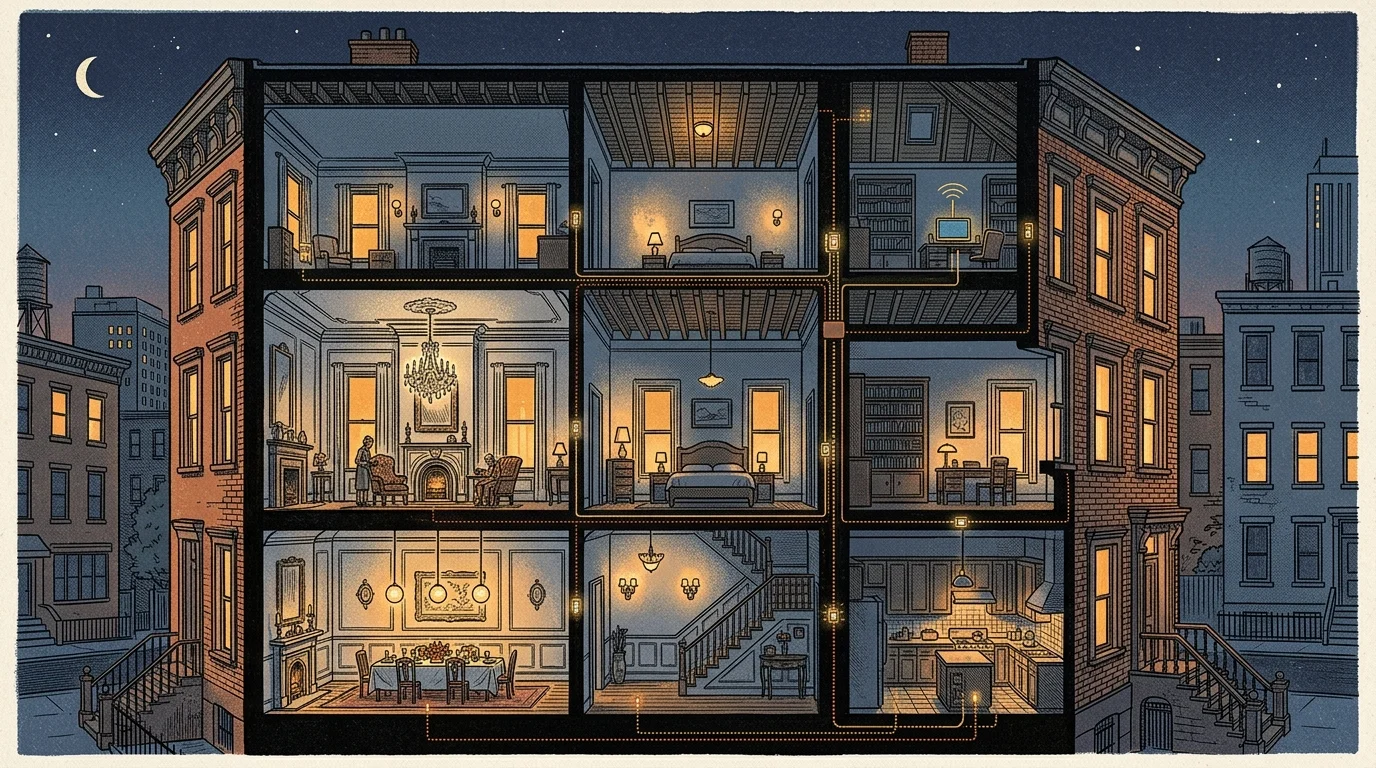
Consider a practical retrofit scenario inside an 1890s Brooklyn brownstone apartment. The living room features a single-gang 3-by-2-by-1.5-inch metal box fed by original flexible armored BX cable.
The circuit controls a central five-arm brass chandelier. The fixture houses five 5-watt dimmable LED candelabra bulbs with individual power factor ratings of 0.92, totaling 25 watts of connected load.
You select a Lutron Diva Smart Dimmer (model DVRF-6L), priced at $69.95. Its rear housing depth measures 1.125 inches (28.6 mm).
Subtracting the switch depth from the 1.500-inch box leaves exactly 0.375 inches (9.5 mm) of rear clearance. You purchase two Wago 221-412 splicing connectors at $0.75 each, which measure 8.3 mm thick.
The calculation confirms the installation parameters:
- Box internal depth: 1.500 inches (38.1 mm).
- Switch body depth: 1.125 inches (28.6 mm).
- Remaining rear cavity: 0.375 inches (9.5 mm).
- Connector thickness: 0.326 inches (8.3 mm).
- Clearance surplus: 0.049 inches (1.2 mm).
The electrical dissipation matches the mechanical clearance. The dimmer draws an off-state standby leakage current of 0.35 mA to keep its sub-GHz radio active.
Dividing 0.35 mA across the five parallel branches yields 0.07 mA per light bulb. Because the driver threshold on these lamps requires at least 0.22 mA to initiate charging, ghosting is impossible.
The entire installation takes 28 minutes to complete and costs $71.45 in total materials. The chandelier operates with smooth low-end dimming down to 10 percent without a single ceiling-mounted bypass capacitor.
Brownstone Lighting Automations and Platform Integration
Once you install a no-neutral switch in your shallow box, connecting it to a smart home platform unlocks automated control. Modern lighting protocols link smoothly to platforms like Apple Home, Home Assistant, and Amazon Alexa.
According to guides from Wirecutter Smart Home, centralized automation hubs dramatically improve smart lighting reliability. Using a dedicated bridge eliminates reliance on fragmented cloud integrations.
Automations allow you to preserve the vintage charm of antique fixtures while enjoying modern convenience. Here are four effective automations tailored for brownstone living:
- Circadian Evening Transition: Automatically adjust living room chandelier brightness down to 40 percent at sunset to prepare your body for rest.
- Hallway Welcome Light: Trigger the entryway fixture to illuminate at 20 percent brightness whenever an exterior door opens after 9:00 PM.
- Vacation Guard Routine: Randomize living room and bedroom lighting within a 30-minute window each evening to simulate occupancy.
- Voice Dimming Presets: Configure spoken commands through Siri or Alexa to adjust vintage sconces to a relaxing 15-percent candlelit glow.
Combining in-wall smart dimmers with modern accent lighting creates balanced illumination across deep brownstone floor plans. You can synchronize vintage chandeliers with warm white light strips tucked along crown moldings.
This layered setup lets you maintain historic architectural aesthetics while enjoying responsive smart lighting throughout your home.
Frequently Asked Questions
Can I install a no-neutral smart switch without a ground wire in a metal box?
Yes, provided the metal box connects to grounded flexible armored cable (BX) or conduit. The switch yoke grounds directly to the metal enclosure via its mounting screws.
Why do my LED bulbs glow dimly when the no-neutral switch is off?
The switch powers its internal radio by trickling a tiny current through the light circuit. If the total load is under 25 watts, this leakage causes faint ghosting.
Do smart switches overheat when installed in cramped shallow metal boxes?
Quality smart dimmers generate negligible heat when operating LED loads under 150 watts. The heavy steel enclosure acts as a heat sink, keeping operating temperatures safe.
Can I use box extension rings in a rental apartment?
Box extension rings increase interior volume but project outward past the wall surface. Landlords frequently object to surface-mounted extension rings because they alter the wall profile.
Disclaimer: This article is for informational purposes only. Smart home devices involve electrical connections and data privacy. Always follow manufacturer instructions for installation. For complex wiring or HVAC work, consult a licensed professional.




1 Comment