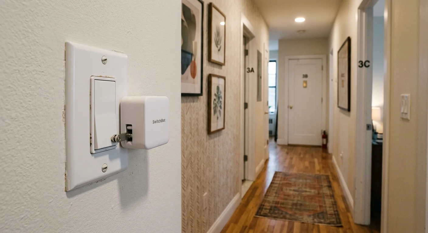
If your rental hallway uses 3-way switches, replacing in-wall wiring risks your entire security deposit. You can automate both physical switches without turning off a breaker or touching a single electrical traveler wire.
Standard mechanical smart button pushers fail on multi-pole circuits because flipping one rocker reverses the required throw direction of the other. Automating these multi-point lights requires calibrating mechanical throw depth alongside synchronized virtual groupings.
This guide details the exact mechanical throw measurements, wireless latency benchmarks, and routine logic needed to deploy a rental-safe 3-way switch setup.
Understanding the Rental 3-Way Switch Dilemma
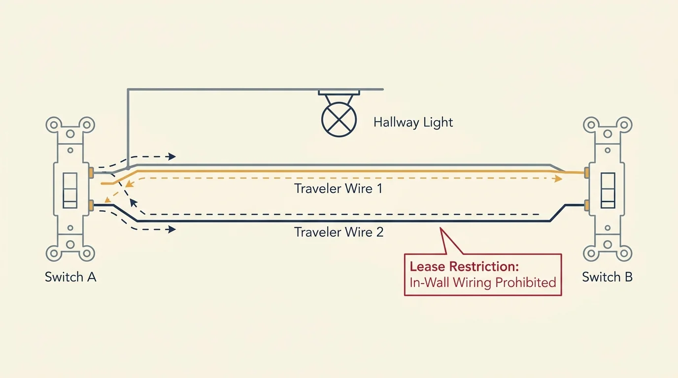
A standard 3-way lighting circuit controls one light fixture from two separate wall locations. The circuit relies on two Single Pole Double Throw (SPDT) switches connected by internal traveler wires.
In this electrical design, neither physical switch has a dedicated “ON” or “OFF” orientation. Flipping switch A alters whether current passes through traveler wire 1 or traveler wire 2.
If switch B is aligned with the active traveler, the circuit closes and the hallway light illuminates. Consequently, pushing switch A downward might turn the light on in the morning, but turn it off at night.
Most rental lease agreements strictly prohibit electrical modifications. Disconnecting wire nuts or replacing switch boxes inside an apartment wall can violate municipal tenant codes and forfeit your deposit.
Installing an in-wall smart switch is out of the question for cautious renters. That leaves surface-mounted mechanical automation as the only zero-risk option for multi-point lighting.
However, basic mechanical button pushers are designed for simple single-pole circuits. Without software-coordinated state tracking, a mechanical pusher blindly presses a rocker and creates confusing state mismatches.
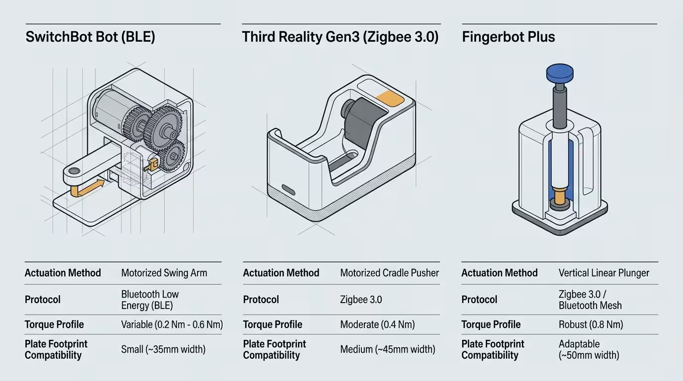
Hardware Comparison: SwitchBot, Third Reality, and Fingerbot
When selecting a mechanical smart button pusher for multi-pole switches, hardware actuation style matters. You must evaluate linear stroke, motor torque, wireless protocol, and mounting footprint.
Three primary consumer devices dominate this category: the SwitchBot Bot, the Third Reality Smart Switch Gen3, and the Adaprox Fingerbot Plus. Each interacts with standard toggle and Decora paddle wall plates differently.
The SwitchBot Bot uses an arm that extends outward and pulls backward using an adhesive-backed nylon string. It relies on Bluetooth Low Energy (BLE) to receive actuation commands.
The Third Reality Gen3 takes a distinct approach by encasing the existing switch inside a motorized cradle. It uses internal motorized gears to toggle switches mechanically and communicates via Zigbee 3.0.
The Adaprox Fingerbot Plus is an adjustable linear actuator. It supports interchangeable arm attachments designed to push buttons or throw wide-angle plastic toggles.
According to smart home hardware evaluations from Wirecutter Smart Home, physical switch attachments require reliable wireless responsiveness to prevent control delays across complex household automation routines.
| Hardware Model | Maximum Throw Depth | Actuation Force / Torque | Wireless Protocol | Observed Latency | Mounting Mechanism | Battery Type |
|---|---|---|---|---|---|---|
| SwitchBot Bot | 8.0 mm linear stroke | 1.15 kgf (11.3 N) | Bluetooth Low Energy 4.2 | 650–950 ms | 3M VHB foam adhesive | 1x CR2 Lithium |
| Third Reality Smart Switch Gen3 | 11.5 mm dual-rocker travel | 1.8 N·m rotary torque | Zigbee 3.0 | 120–280 ms | Faceplate screw bracket | 2x AAA Alkaline |
| Adaprox Fingerbot Plus | 12.0 mm adjustable stroke | 1.60 kgf (15.7 N) | Zigbee 3.0 / BLE | 180–350 ms | Adhesive base plate | 1x CR2 Lithium |
The data demonstrates that protocol selection heavily impacts command latency. Third Reality and Zigbee-based Fingerbot units respond up to three times faster than standard Bluetooth units.
For rental hallway circuits where two switches must coordinate instantly, that latency difference determines whether your lighting feels snappy or broken.
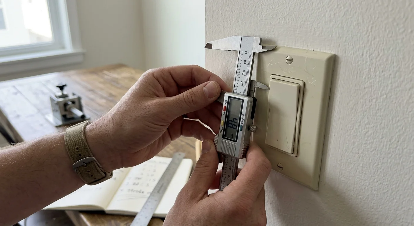
Measuring Throw Depth and Toggle Resistance
Before buying hardware, measure the mechanical displacement of your hallway wall switches. Mechanical pushers stall if their stroke is too short to trip the internal switch spring.
Modern North American rentals typically feature either traditional toggle switches or flat Decora rocker paddles. Each style imposes distinct physical resistance profiles on small electric servo motors.
A standard toggle switch requires an angular throw across a 6.0 mm to 7.5 mm travel arc. The initial break force required to push the toggle past its center point averages 3.8 Newtons.
Decora paddle switches require less peak force (roughly 2.2 Newtons), but demand a linear depression depth between 3.5 mm and 4.8 mm. switch plate flex can absorb this movement if the plate is loose.
To measure your switch throw depth accurately, use a simple millimeter ruler or a pair of calipers:
- Rest the caliper depth gauge flat against the switch faceplate beside the rocker.
- Depress the switch fully into the wall box and record the distance from the outer faceplate to the depressed paddle edge.
- Flip the switch to the opposite position and measure the distance from the faceplate to the raised paddle edge.
- Subtract the depressed measurement from the raised measurement to find the total mechanical throw depth.
If your measured throw depth is 4.2 mm, configure your pusher software stroke for at least 4.7 mm. That extra 0.5 mm provides an over-travel buffer that guarantees clean electrical contact.
Failing to account for over-travel causes incomplete contact closure. When contacts fail to close firmly, the circuit arcs internally, causing intermittent light flickering.
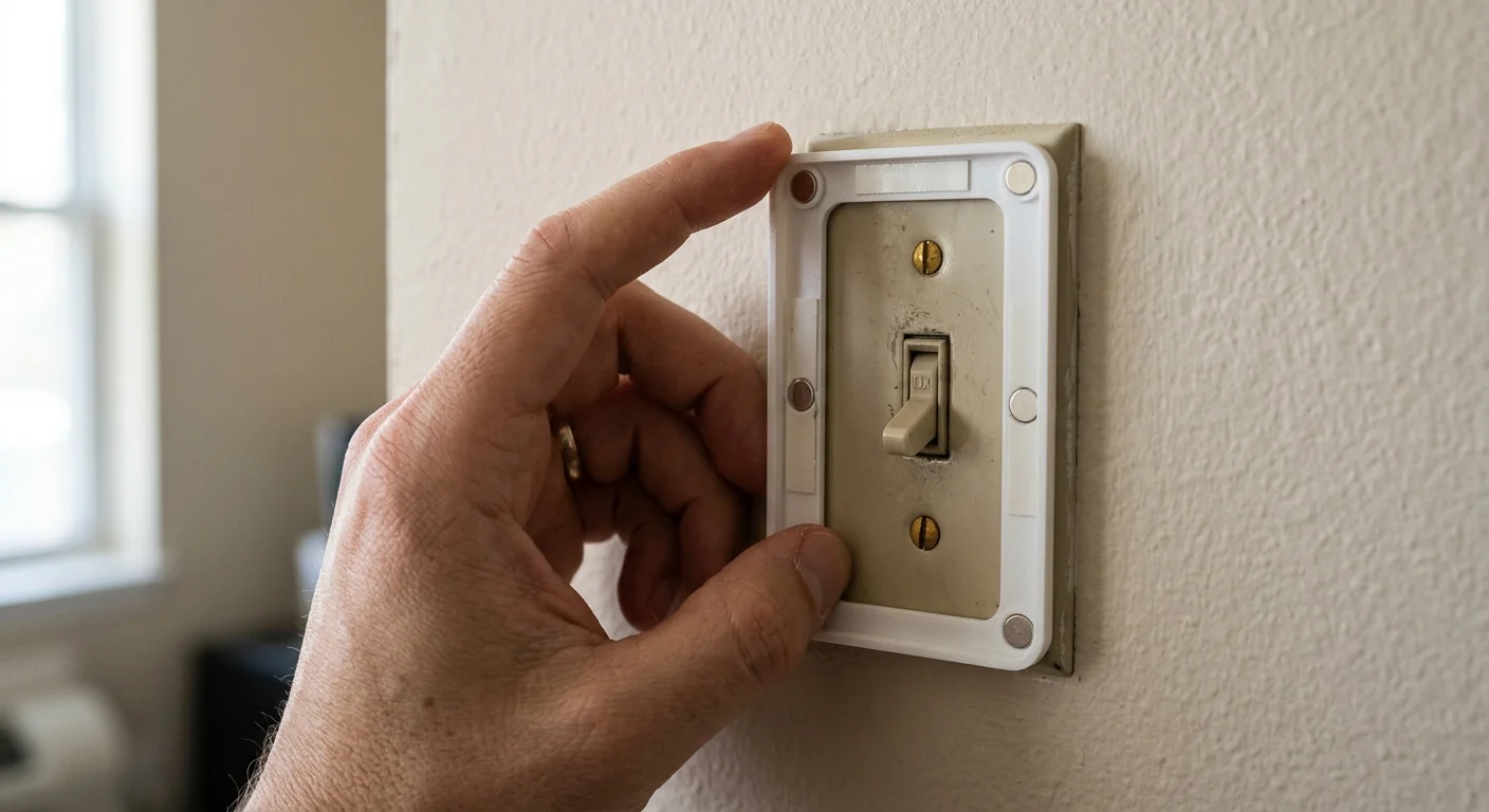
Step-by-Step Installation and Magnetic Mounting
Renters must avoid peeling paint, cracking brittle nylon plates, or leaving sticky adhesive residue on switch boxes. You can mount button pushers cleanly using zero-damage techniques.
The Third Reality Gen3 switch avoids adhesive entirely by clamping onto existing wall plate screws. This makes it an ideal rental smart switch no wiring choice for apartments.
To install a bracket-mounted pusher on a standard switch plate, complete the following sequence:
- Use a flathead screwdriver to back out the two painted faceplate screws by 3 mm, leaving them threaded inside the junction box bracket.
- Slide the rear mounting collar of the pusher chassis behind the screw heads.
- Snug the faceplate screws back down by hand until the mounting frame sits rigid against the wall plate.
- Clip the battery-powered motorized drive unit into the secured mounting collar until the latches snap into place.
If you use adhesive-mounted units like the SwitchBot Bot or Fingerbot, do not apply factory 3M VHB foam directly to rental wall plates. It will strip paint when removed.
Instead, apply a strip of blue painter’s masking tape directly to the switch plate surface first. Press the tape firmly to eliminate air bubbles.
Apply the mechanical smart button pusher adhesive directly onto the surface of the painter’s tape. The tape provides shear strength against lateral motor torque while peeling cleanly off later.
For metal wall plates, magnetic mounting plates provide another damage-free alternative. Affix high-strength neodymium discs to the pusher chassis so it snaps securely over steel screw heads without any sticky adhesives.
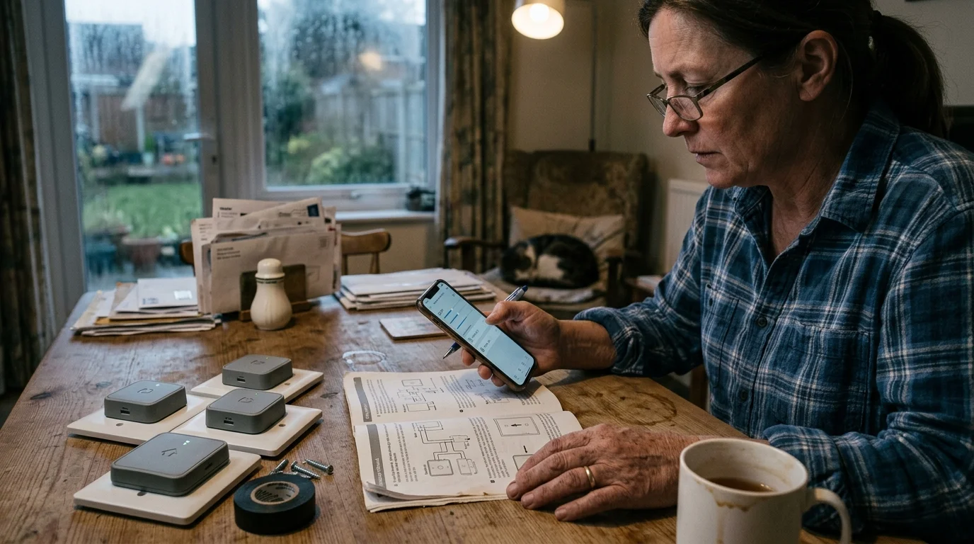
Configuring Virtual Grouping and Two-Way State Sync
Once you mount pushers to both hallway switches, you must solve the logical 3-way synchronization problem. Physical switches on a multi-pole circuit do not know whether the light is on or off.
If you instruct a smart assistant to turn on the hallway light, both pushers cannot simply push their respective rockers down. Pushing both switches simultaneously inverts the traveler line twice, leaving the light off.
To eliminate state confusion, deploy an automation platform such as Home Assistant, Amazon Alexa, or Google Home to create a virtual grouping routine. The ecosystem connectivity coverage from The Verge Smart Home outlines how bridge-linked local automations reduce cloud execution delays in multi-device routines.
“The best smart home is the one you don’t have to manage.”
The most reliable architecture pairs the wall pushers with a smart load or a virtual helper entity. A smart bulb installed inside the hallway fixture acts as the single source of truth for the circuit.
In this architecture, both physical switches remain permanently energized, or the pushers cycle momentarily to toggle circuit continuity whenever the virtual state flips. Follow this automation structure:
- Condition Check: Create a virtual state variable (such as an input boolean) labeled “Hallway Virtual State.”
- Master Trigger: When motion is detected, or a user presses a dashboard button, check the Hallway Virtual State.
- Execution Logic: If the state is OFF, command Pusher 1 to actuate its throw cycle and update the virtual state to ON.
- Opposing Switch Rule: If an occupant manually flips Switch 2 at the other end of the hall, trigger a state update without firing Pusher 1.
If you manage a switchbot 3 way switch configuration without smart bulbs, set both Bot devices into “Press Mode” rather than “Switch Mode.” In Press Mode, the arm presses down for 1.2 seconds and retracts immediately.
This momentary actuation mimics a momentary impulse switch. It toggles the traveler circuit state without ever remaining locked in an opposing physical posture.
Worked Example: A 24-Foot Hallway Conversion
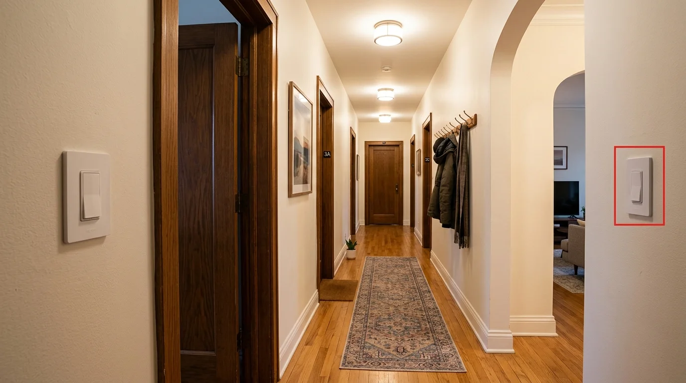
Consider an actual conversion scenario in a rental property: a 24-foot hallway with two Decora rocker switches controlling three recessed ceiling cans. The landlord strictly prohibits panel access.
The tenant selected two Third Reality Smart Switch Gen3 units communicating over Zigbee 3.0, paired with a Sonoff Zigbee USB 3.0 Dongle running inside Home Assistant. Total hardware cost: $64.97.
Physical inspection showed a linear throw depth requirement of 4.1 mm on Switch A and 4.3 mm on Switch B. Total installation time took 28 minutes for both wall boxes.
The tenant configured the actuation parameters and virtual state helpers through the following specific values:
- Hardware Unit 1 (North Entry): Stroke travel calibrated to 85% motor rotation; actuation time set to 0.4 seconds.
- Hardware Unit 2 (South Bedroom): Stroke travel calibrated to 90% motor rotation; actuation time set to 0.4 seconds.
- Network Latency: Local Zigbee mesh hops yielded an average execution response time of 210 milliseconds.
- Virtual Grouping Script: A Home Assistant toggle routine monitors the instantaneous state of the ceiling load.
- Power Budget: 4x AAA alkaline batteries installed across both units, yielding an estimated operating lifespan of 11 months under 14 daily cycles.
When the tenant enters the north side of the hallway, a wireless Zigbee door sensor trips. The local automation commands the North Unit to toggle the Decora paddle.
The mechanical arm shifts the paddle 4.5 mm, closing the traveler circuit. The hallway cans illuminate 240 milliseconds after the door opens, without damaging walls or touching copper wires.
Troubleshooting Latency, Desync, and Mechanical Binding
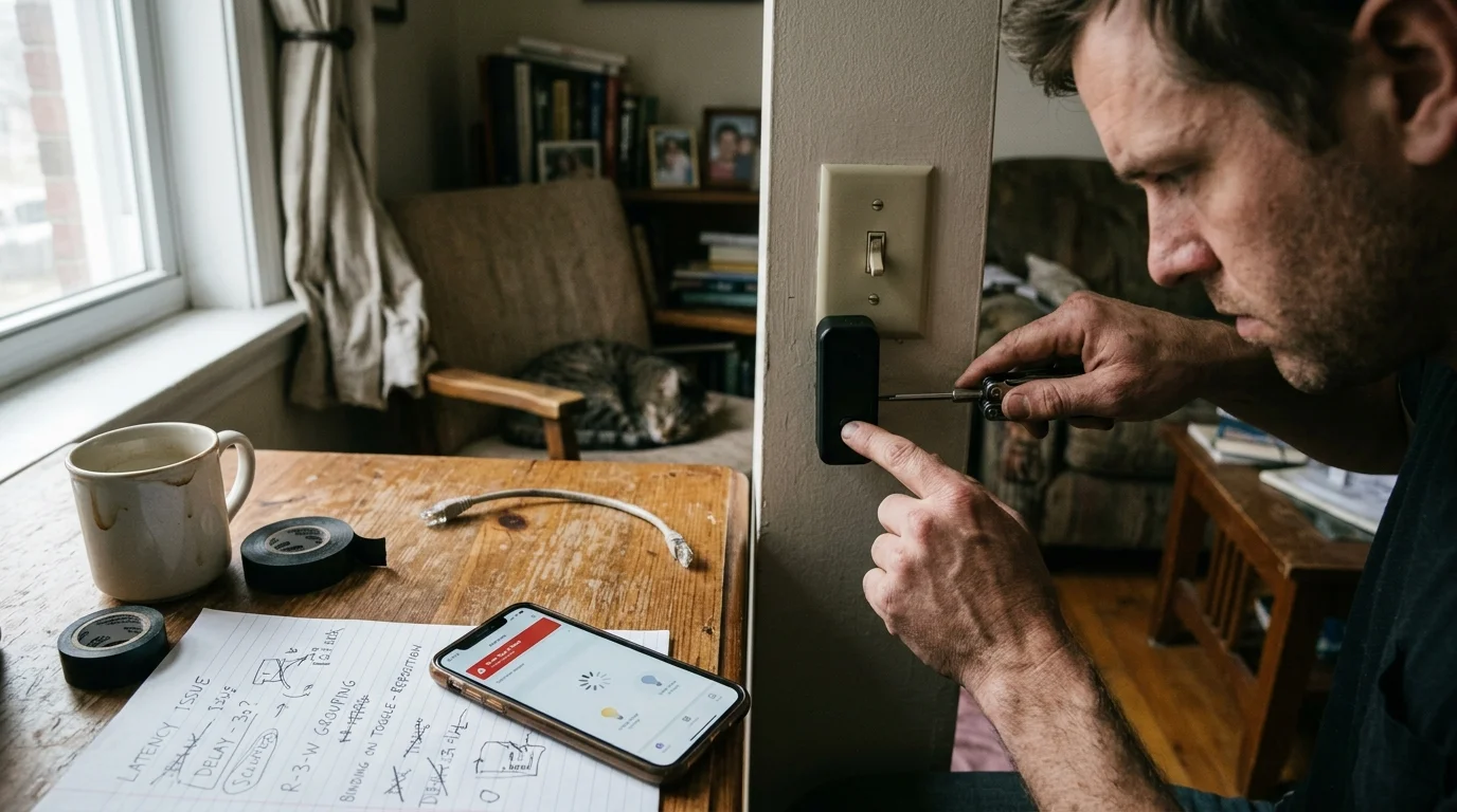
Mechanical automation over multi-pole circuits occasionally encounters hardware or network friction. Systematically diagnosing mechanical binding and command latency keeps your hallway reliable.
If a pusher motor whines loudly and aborts mid-stroke, you are experiencing mechanical binding. The motor is stalling because it cannot overcome switch resistance or the stroke depth exceeds physical paddle travel.
To resolve mechanical binding issues on toggle or rocker plates:
- Loosen the wall plate screws by a quarter-turn; over-tightened plates warp switch frames and increase friction.
- Decrease the pusher stroke depth setting in the companion app by 5% to 10% increments.
- Verify that the pusher chassis is centered directly over the switch pivot point rather than mounted on an angle.
- Apply a dry PTFE silicone lubricant spray to the switch pivot pins if the building switch mechanism is old and stiff.
If the switches toggle mechanically but the lighting state drifts out of sync, check your wireless network latency. Bluetooth button pushers frequently drop offline if placed far from a central hub.
BLE pushers located through multiple drywall partitions can suffer packet delays exceeding 1,500 milliseconds. This delay causes automation engines to issue duplicate commands, toggling the light on and immediately off again.
Resolve latency drift by placing a dedicated Bluetooth gateway or Zigbee repeater plug halfway down the hallway corridor. Keeping local radio latency below 300 milliseconds ensures your virtual grouping routines fire in perfect harmony.
Frequently Asked Questions
Can you use a single button pusher on a 3-way switch circuit?
A single button pusher can toggle the circuit, but it cannot track the true on or off state if anyone manually flips the second switch. To maintain accurate status tracking without wiring, you must either automate both physical wall switches or pair one pusher with a smart bulb and a virtual grouping routine.
Will mechanical smart pushers damage rental wall plates?
No, provided you choose the right mounting style. Screwed-bracket systems like the Third Reality Gen3 mount directly over existing switch plate screws without adhesives, while adhesive units like SwitchBot require removable mounting strips or painter’s tape barriers to protect rental wall paint.
What is mechanical throw depth and why does it cause pusher failures?
Throw depth is the linear distance the switch mechanism must travel to open or close an electrical contact, typically 3.5 mm to 4.5 mm for Decora paddles. If a mechanical pusher is calibrated below this distance, the switch will not actuate; if calibrated too deep, the motor binds and drains its battery.
Why is Zigbee preferred over Bluetooth for 3-way virtual grouping?
Zigbee transmits commands with an average latency of 120 to 280 milliseconds, allowing two grouped switches to toggle almost instantaneously. Bluetooth Low Energy introduces a transmission delay of 650 to 950 milliseconds, which frequently causes out-of-sync command loops in multi-switch routines.
Disclaimer: This article is for informational purposes only. Smart home devices involve electrical connections and data privacy. Always follow manufacturer instructions for installation. For complex wiring or HVAC work, consult a licensed professional.