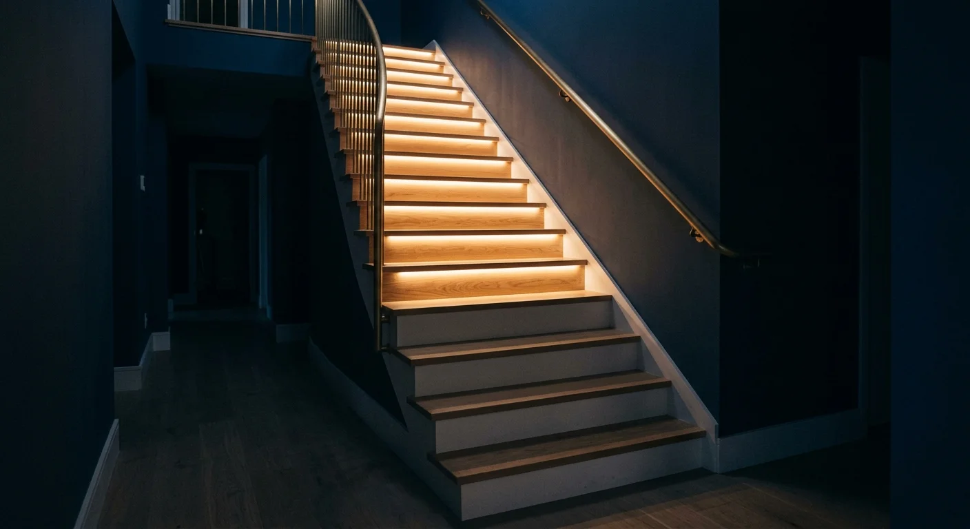
Carrying a groggy toddler down an unlit 16-step staircase during a 2:00 AM feeding requires both hands on your child and zero fumbling for wall switches.
Standard motion detectors blind dark-adapted eyes with sudden glare or trigger after you already step onto unlit treads. Worse, prowling house cats constantly trip general-purpose sensors.
Calibrating your sequential stair lighting automation to an exact 180-millisecond step cascade while mounting narrow-beam sensors at 28 inches eliminates pet triggers and illuminates treads safely ahead of your footfalls.
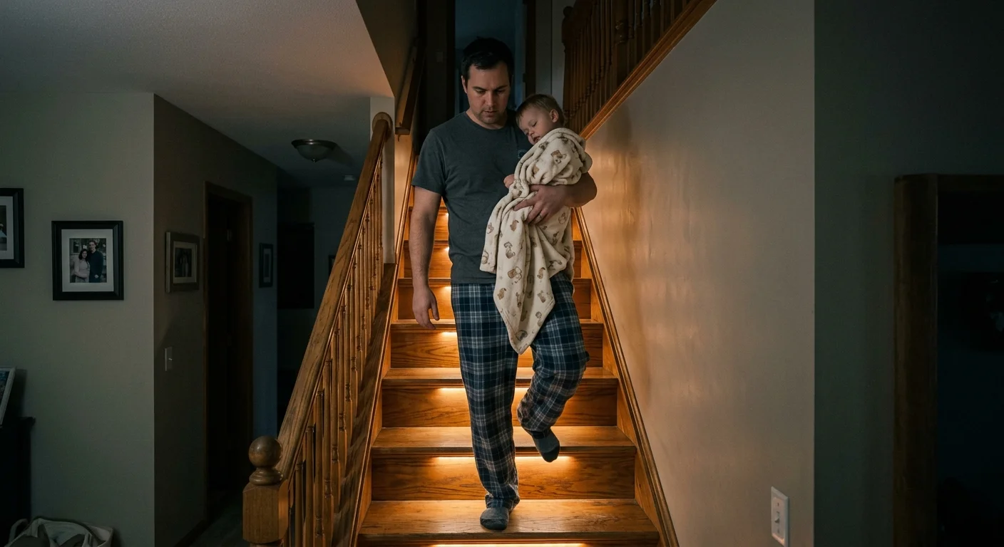
Stairway Safety Physics and Toddler Night-Navigation Realities
Navigating stairs in the dark while holding a child changes your balance mechanics. Your downward peripheral line of sight is obstructed, forcing reliance on muscle memory and clear visual edge contrast.
Pairing sequential step lighting with broader smart home routines for parents with young children ensures reliable nighttime visibility between bedrooms, nurseries, and downstairs areas.
Beyond basic tread visibility, preventing inquisitive toddlers from disabling nighttime lighting pathways follows the same principles as childproofing smart light switches in adjacent hallways and nurseries.
According to National Electronic Injury Surveillance System data published in The American Journal of Emergency Medicine, an average of 1,076,558 patients receive emergency department treatment annually for stair-related falls.
The study highlights that fall injury rates per capita peak among children under age five and older adults. Carrying an infant doubles the risk profile during overnight transitions.
Building codes recognize these hazards directly. The International Residential Code (IRC Section R303.7) mandates interior stairway illumination of not less than 1 foot-candle (11 lux) measured directly at the center of treads and landings.
Critically, IRC Section R303.7 includes an exception allowing automatic, sensor-driven controls to replace manual three-way wall switches. This exception legalizes dedicated sequential stair lighting automation when designed properly.
Uniform step illumination prevents edge disorientation. When lighting activates sequentially from your entry point, your eyes track the path naturally without triggering night blindness.
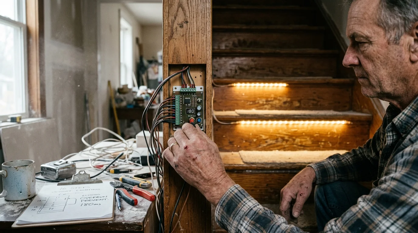
The 180ms Cascade Timing Rule: Preventing Overrun on 16 Steps
Stair step speed requires precise timing. Typical adult and child stair descent cadences average between 500 and 700 milliseconds per step tread under normal domestic conditions.
Similar to programming low-lux dimming curves, configuring a gradual fade instead of a sharp shutoff prevents eye strain after the hold timer expires.
If your sequential lighting controller triggers steps slower than your travel cadence, you step onto dark surfaces. A cascade set at 600 milliseconds per step takes 9.6 seconds to illuminate 16 steps.
At that sluggish rate, an adult descending at 550 milliseconds per step reaches step five before the lights hit step four. You outrun the illuminated sequence entirely in the dark.
Conversely, instantaneous lighting bursts produce severe pupillary constriction. A rapid flash ruins dark adaptation, leaving you momentarily blinded while holding your child.
Setting your cascading step interval to exactly 180 milliseconds solves both safety problems. At 180 milliseconds per tread, a 16-step staircase fully illuminates in precisely 2.88 seconds.
As you take your initial footfall on step one (550 milliseconds), steps one through four are already bright. The light wave stays three steps ahead of your movement.
When ascending from the bottom landing, the 180-millisecond rate produces identical forward illumination. The staircase creates an inviting path upward without strobing or lagging behind your gait.
Hold time matters just as much as cascade speed. Configure your main controller to hold illumination for 20 seconds after the final step fires before initiating the sequential fade-out.
Pet Immunity Engineering: Narrow-Beam Sensors and Optical Masking
Household pets ruin automated stair systems when sensors use wide-angle passive infrared (PIR) detectors. A standard 120-degree PIR dome triggers whenever a ten-pound cat strolls near the lower landing.
Homeowners troubleshooting persistent false alerts near feline corridors can apply similar physical isolation principles used in directional mmWave micro-zones to separate pet pathways from human foot traffic.
For families managing adventurous toddlers, landing sensors can also integrate with zero-latency door open chimes to provide immediate audio warnings if an unassisted descent begins.
Much like tuning outdoor PIR sensors to ignore wildlife, filtering domestic animals indoors requires establishing physical optical boundaries instead of relying on software sensitivity sliders.
Constant false triggers disrupt family sleep and run down hardware lifespans. Effective pet-immune design relies on optical geometry and physical mounting height rather than software weight approximations.
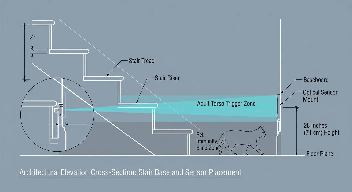
To eliminate feline triggers, mount your smart stair sensors precisely 28 inches (71 centimeters) above the finished floor level on both top and bottom landings.
Household cats measure under 12 inches at the shoulder and rarely exceed 16 inches in walking height. Setting the detection plane at 28 inches creates an invisible bypass zone beneath the beam.
Meanwhile, the average two-year-old child stands roughly 33 to 34 inches tall. An upright toddler walking toward the steps breaks the sensor plane at chest height without fail.
When carrying your child, your adult torso breaks the sensor plane across mid-abdomen height. The controller initiates the cascade reliably every single time.
Standard PIR sensors require beam narrowing to prevent false perimeter triggers. Apply non-reflective electrical tape over the outer perimeter of the PIR Fresnel lens, exposing only a two-millimeter vertical center slit.
This optical masking restricts the sensor field of view from 120 degrees down to roughly 15 degrees. The detector ignores pets pacing across the hallway and only fires when bodies enter the stair path.
Time-of-Flight (ToF) laser micro-sensors provide an even more accurate alternative. Devices like the VL53L1X emit invisible infrared photons, triggering strictly when an obstacle enters an exact distance threshold between 20 and 40 inches.
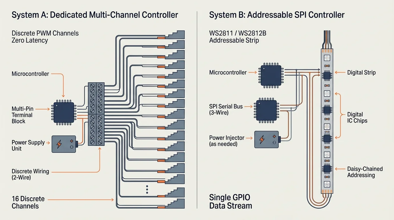
Hardware Architecture: Dedicated Controllers vs Addressable Systems
Selecting the right hardware platform dictates wiring complexity, reliability, and tuning granularity. You have three primary architecture options for sequential stair illumination.
Mounting low-profile aluminum profiles beneath tread nosings utilizes the same principles as diffused under-rail channels, shielding bare diodes from upward sightlines.
Operating stair cascades as a standalone subsystem prevents mesh network congestion from slowing down your broader smart lighting zones.
| Hardware Architecture | Cascade Tuning Range | Wiring Topology | Pet Filtering Capability | Hardware Cost (16 Steps) |
|---|---|---|---|---|
| Dedicated Multi-Channel DC (e.g., SP32, CT3252) | 150ms to 1,600ms per tread | Homerun 2-conductor wire to each step | Hardware-adjustable optical or ToF sensors | $35 to $75 (controller only) |
| Addressable Pixel Controller (e.g., QuinLED Dig-Quad / WLED) | 10ms to 2,000ms via software | Single 3-wire continuous data run | Requires external smart home sensor integration | $60 to $110 (board and ESP32) |
| Mains Smart Relay System (Zigbee or Matter) | 500ms minimum (cloud/mesh latency) | Standard line voltage in-wall junction | Relies on ecosystem motion sensors | $180 to $300 (multiple relays) |
Dedicated multi-channel DC controllers, such as the CT3252 or SP32 series, offer the most dependable performance. They feature physical screw terminals for 16 to 32 individual LED outputs.
These units run autonomous firmware on internal microcontrollers. They do not depend on Wi-Fi connectivity, cloud servers, or home automation hubs to fire their cascading sequence.
Addressable LED setups running digital pixel strips offer extraordinary aesthetic control. However, a single severed data pin halts lighting for every subsequent step down the staircase string.
Mesh ecosystem relays operating on Zigbee or the Matter smart home standard introduce network latency. Mesh signals often take 300 to 800 milliseconds just to propagate between switches, ruining cascade fluidity.
For uniform illumination without harsh point reflections, install continuous-phosphor COB (Chip-on-Board) LED strips. COB strips eliminate diode spotting across shiny hardwood or painted stair risers.
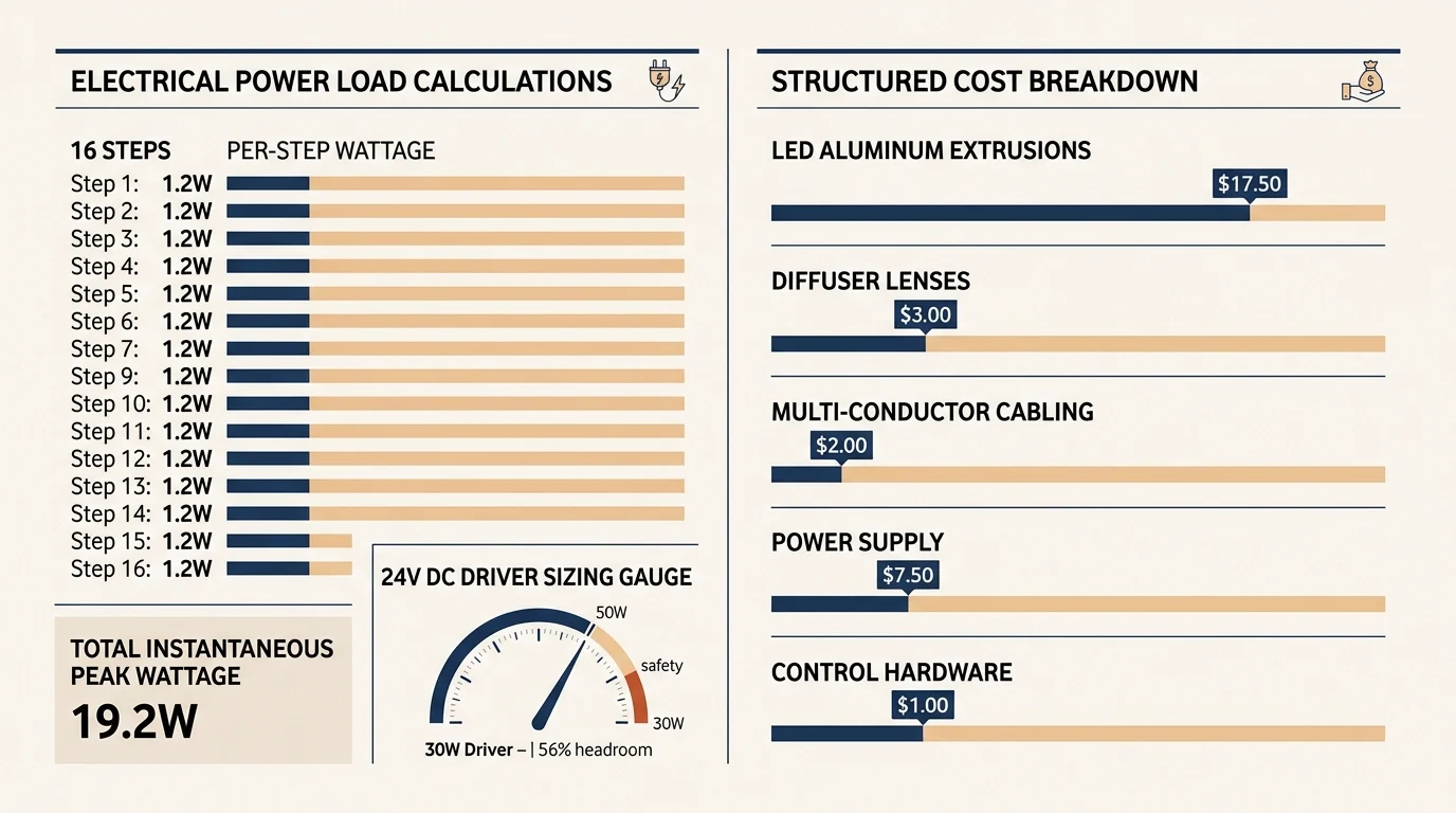
Worked Example: Total Cost and Power Load for a 16-Step Installation
Let us review a real-world worked example for an unlit 16-step straight interior staircase. Each tread measures 36 inches in total width.
When tucking controllers beneath the steps, separate the stair driver circuits from fixtures designated for under-stair home offices to prevent electrical noise and voltage drops.
Much like sizing transformers for low-voltage landscape lighting, budgeting an electrical buffer prevents continuous-load drivers from overheating inside enclosed walls.
To eliminate edge glare and center the beam, install a 31.5-inch (0.8-meter) strip of 24V Warm White (2700K) COB LED lighting beneath each stair nosing.
The chosen strip draws 6 watts per linear meter at full load. Each 0.8-meter step riser therefore consumes 4.8 watts of power.
Calculate maximum continuous power draw by multiplying step load across all 16 treads: 16 treads multiplied by 4.8 watts equals 76.8 watts total power demand.
Power supplies must never operate at maximum continuous capacity. Applying an 80 percent safety margin requires dividing 76.8 watts by 0.8, establishing a minimum 96-watt power supply threshold.
A Mean Well LPV-100-24 (24V DC, 100-watt, IP67 Class 2 power supply) matches this demand safely for $38. It operates silently without internal cooling fans.
The project budget breaks down across the following specific parts:
- One CT3252 32-channel cascading stair light controller: $45
- One Mean Well LPV-100-24 power supply unit: $38
- 13 meters of 24V COB LED strip (2700K, 384 chips/m): $42
- Two narrow-beam infrared sensors with 28-inch mounting plates: $24
- 16 pieces of 1-meter aluminum surface channels with milky diffusers: $46
- 100 feet of 20 AWG 2-conductor copper hookup wire: $16
The total hardware expenditure equals $211. Installation requires approximately 4.5 hours of assembly time during a weekend project window.
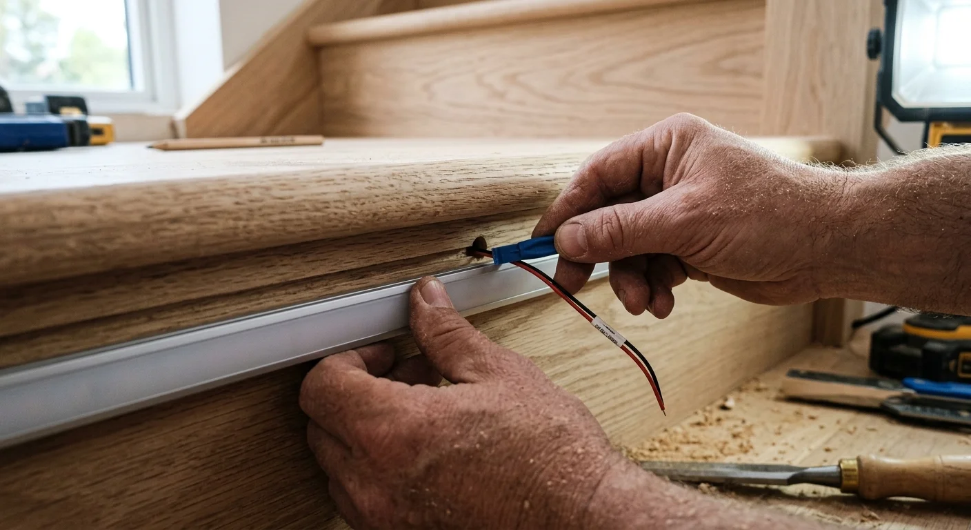
Step-by-Step Installation: Channels, Homerun Wiring, and Logic
Execute installation systematically to maintain electrical safety and prevent visible wire clutter. Ensure mains power is switched off at the breaker panel before touching existing electrical boxes.
If the cavity beneath your staircase has been converted into a finished nook or windowless under-stair home office, map your homerun wire paths carefully to prevent electromagnetic interference with nearby computer equipment.
- Mount the aluminum channels beneath each stair nosing. Fasten each channel with counter-sunk wood screws, directing the lighting downward toward the tread surface to avoid upward glare.
- Wipe aluminum channels with isopropyl alcohol. Adhere the cut-to-length 0.8-meter COB LED strips inside, snapping the milky diffuser covers securely into place over the diodes.
- Drill a 3/16-inch hole on the hidden stringer side of each riser. Pass your 20 AWG 2-conductor homerun wire through the riser into the under-stair storage area or utility access panel.
- Route each 2-conductor wire back to the central controller location. Label both ends of every wire carefully with riser numbers (Step 1 through Step 16) using wire marking tape.
- Mount the bottom landing sensor at exactly 28 inches above the floor. Position it perpendicular to your walking path, five inches forward from the initial riser.
- Mount the top landing sensor at 28 inches above the upper floor surface. Aim the narrow beam across the approach path to catch footsteps before feet descend onto the first step.
- Terminate each wire pair into the terminal block of the controller. Match positive and negative polarity on channels 1 through 16 sequentially from bottom to top.
- Connect the 24V DC power supply outputs to the primary input terminals of your controller, observing correct polarity.
- Power on the controller and use the onboard programming buttons to select 16 connected channels, set step delay to 180 milliseconds, and configure hold duration to 20 seconds.
Always verify wire gauge across long runs to eliminate voltage drop. Steps near the top of the run require longer wire lengths than lower steps.
For runs under 30 feet at 0.2 amps (4.8 watts at 24V), 20 AWG copper wire keeps voltage drop below 1.2 percent. This consistency prevents dimming on higher risers.
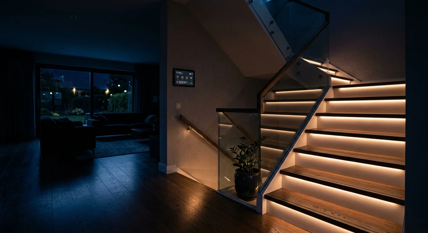
Circadian Dimming and Smart Ecosystem Integration
Stair lighting brightness must adapt to environmental context. Lighting that looks comfortably subtle at 8:00 PM will painfully dazzle your eyes during a 2:00 AM nursery run.
Integrate circadian control by pairing your DC power supply with an upstream smart dimmer or switching relay. Connect the power supply primary AC plug to an automated smart wall outlet.
Configure your smart home platform to schedule two distinct brightness modes based on time of day. Major smart home platforms easily manage these automated shifts, as detailed in The Verge’s smart home coverage.
Program Daytime Mode from 7:00 AM to 9:00 PM at 100 percent controller output. This level overcomes ambient sunlight washing through nearby windows and defines step edges clearly.
Program Nighttime Nursery Mode from 9:01 PM to 6:59 AM, limiting controller duty cycle output to 20 percent. This produces approximately 2 foot-candles at the tread center.
This 2-foot-candle illumination clears the IRC R303.7 1-foot-candle legal threshold easily. Simultaneously, it avoids pupil shock and preserves night vision for both parent and child.
Select color temperatures between 2400K and 2700K. Warm light wavelengths avoid melatonin disruption during critical overnight feeding and diaper changes.
Frequently Asked Questions
Why is a 180-millisecond delay preferred over a 500-millisecond delay?
A 500-millisecond delay per step takes eight seconds across 16 stairs, meaning your descent outpaces the light sequence. A 180-millisecond delay takes 2.88 seconds total, projecting illumination safely ahead of your steps.
Can a climbing cat trigger a stair sensor mounted at 28 inches?
A cat walking along the floor passes underneath a 28-inch beam without triggering. However, if a cat jumps onto a banister or stair rail at that exact height, it will break the beam.
Does sequential stair lighting meet local building electrical codes?
Yes, IRC Section R303.7 allows automated sensor control systems in place of conventional three-way wall switches, provided center-tread illumination maintains at least 1 foot-candle (11 lux).
Why are 24V LED strips recommended over 12V versions for stairs?
24-volt systems carry current with half the amperage of 12-volt systems for equal wattage. This reduction minimizes voltage drop over long wiring runs from the controller to upper steps.
Disclaimer: This article is for informational purposes only. Smart home devices involve electrical connections and data privacy. Always follow manufacturer instructions for installation. For complex wiring or HVAC work, consult a licensed professional.