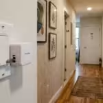
Arriving home from an intensive care unit shift at 03:30 requires navigating an 800-square-foot apartment without waking your partner on a daytime schedule. Overhead fixtures immediately flood adjacent bedrooms with photon scatter that shatters restorative sleep.
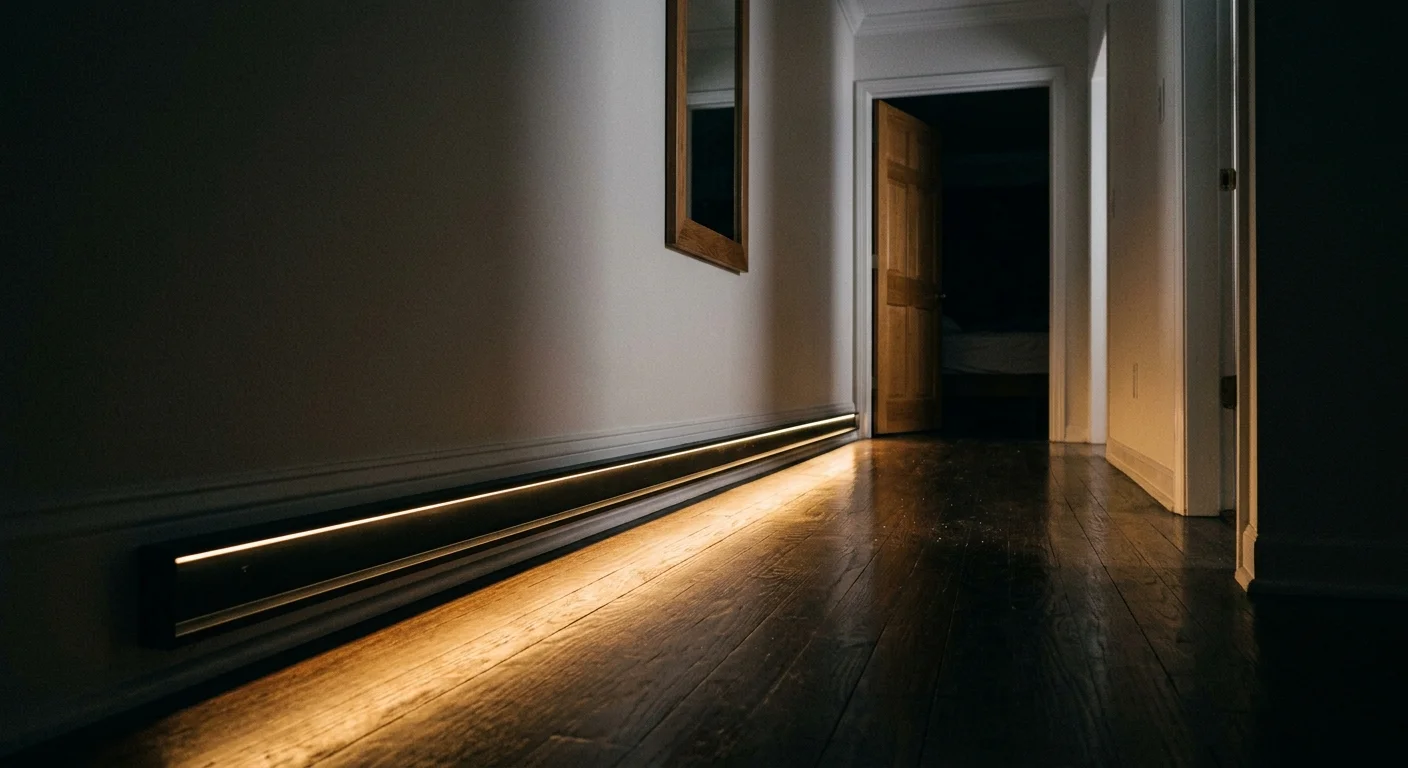
Standard hallway nightlights cast unshielded glare across 24-inch mattress horizons. Angling low-profile channels beneath baseboards confines luminous flux entirely to the flooring plane, eliminating sleep-disturbing vertical spill.
This technical guide details deflector channel geometry, low-lux sensor millivolt thresholds, and Class 2 electrical configurations. You will protect your partner’s circadian rest while maintaining safe navigational visibility for yourself.
Circadian Biology and the Photometric Threat to Shift Workers
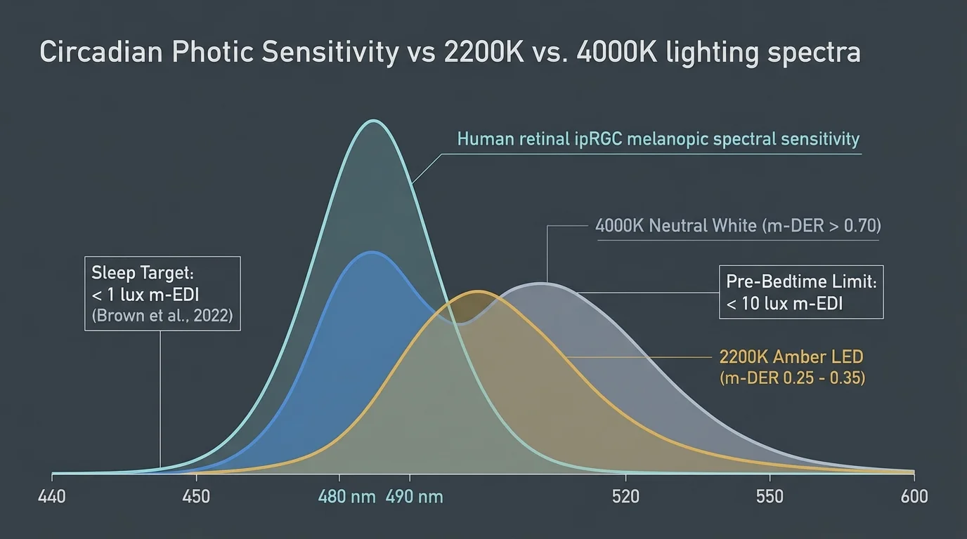
Your retina contains intrinsically photosensitive retinal ganglion cells (ipRGCs) that govern circadian rhythm through the photopigment melanopsin. These non-visual photoreceptors exhibit peak spectral sensitivity between 480 and 490 nanometers.
Healthcare and industrial employees working irregular hours often combine low-level baseboard runs with dedicated red spectrum nightlight automations to prevent sleep architecture disruption during off-shift rest.
Exposure to blue-green wavelengths triggers an immediate neural signal to the suprachiasmatic nucleus. This biological command suppresses endogenous melatonin secretion and forces systemic vigilance.
The primary driver of human circadian entrainment is environmental light captured by ipRGCs, where short wavelengths exert the strongest biological disruption.
A landmark scientific consensus published in PLOS Biology (Brown et al., 2022) established rigid indoor thresholds. The researchers recommend an environment below 1 lux Melanopic Equivalent Daylight Illuminance (m-EDI) during sleep.
Pre-bedtime exposures require levels under 10 lux m-EDI to prevent phase-shifting the human master biological clock. Daytime alertness, by contrast, demands a biological stimulus exceeding 250 lux m-EDI.
Standard 4000K neutral white architectural lighting yields a high Melanopic Daylight Efficacy Ratio (m-DER) exceeding 0.70. Diodes calibrated to ultra-warm 2200K amber drop this ratio to roughly 0.25 to 0.35.
This lower biological coefficient allows you to produce adequate photopic illumination across baseboards for safe movement. Simultaneously, you expose sleeping eyes to only a fraction of the circadian disruption.
The WELL Building Standard v2 Feature L03 reinforces this approach for evening residential environments. The standard sets a strict limit of 50 Equivalent Melanopic Lux (roughly 45 m-EDI) at 30 inches above the finished floor.
Balancing two conflicting work routines inside an 800-square-foot floor plan leaves zero margin for photometric error. You must direct every single lumen downward.

Optical Geometry: Calculating Angles to Eliminate Mattress-Level Spill
Standard apartment door undercuts measure between 0.5 inches and 0.75 inches above hardwood or tile flooring. Standard mattress surfaces sit 22 to 26 inches above the finished floor level.
Any light vector that bounces off a polished corridor floor at an upward angle penetrates this door gap. It strikes the eye level of a sleeping partner lying in bed.
Eliminating mattress spill requires managing two optical factors: fixture beam angle and internal reflection within the aluminum extrusion channel. Standard bare tape disperses light across a wide 120-degree Lambertian distribution profile.
Flush ceiling mounts or unshielded perimeter coves throw light directly against opposite walls. That scattered bounce creates vertical illumination gradients that easily exceed 5 lux at mattress height.
Recessed under-baseboard channels with asymmetric 30-degree or 45-degree internal deflector flanges control this trajectory. The extruded aluminum fin cuts off all horizontal photon discharge above a 15-degree departure line.
- Asymmetric 45-degree profiles: Cast light down and outward across a narrow 18-inch floor margin without illuminating opposite walls.
- Deep-recessed vertical profiles: Drop light directly into the expansion gap between flooring planks and drywall baseboards.
- Micro-louvered diffusers: Eliminate direct sightlines to the phosphors from any angle higher than 4 inches above the floor.
- Matte floor finishes: Prevent specular reflections from bouncing light rays upward into cracked bedroom doorways.
You can calculate the spatial illuminated margin on your floor using standard right-triangle trigonometry. Multiply the baseboard channel elevation by the tangent of the fixture shield cutoff angle.
A channel mounted 3.5 inches above finished floor with a 30-degree deflector shield produces an active beam limit of 2.02 inches. Photons strike the ground directly below the molding rather than projecting upward.
Floor surface finishes determine secondary bounce characteristics. Gloss-finished oak yields a specular reflection coefficient near 0.08, whereas matte polyurethane holds specular bounce under 0.015.
Selecting directional extrusions rather than open LED ribbons keeps the primary reflection cone flat. The light stays below bedroom threshold sightlines at all times.
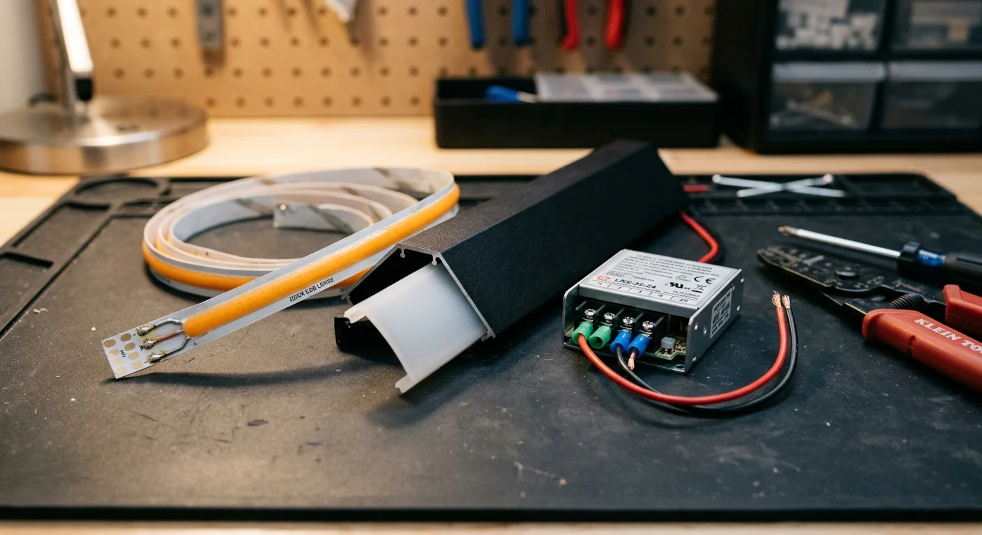
Hardware Selection: Drivers, 2200K COB Strips, and Extrusions
Traditional surface-mount diode (SMD) strips create visible hot spots along polished hallway floors. These uneven points of bright light produce uncomfortable contrast against dark bedroom corridors.
Chip-on-Board (COB) LED strips solve this issue using a continuous phosphor coating across dense diode arrays. Selecting 384 to 528 diodes per meter ensures an uninterrupted ribbon of gentle amber light.
Your hardware must maintain a stable color temperature without chromaticity shifts across ultra-low dimming thresholds. Inspect verified lab tests before buying, as detailed in Wirecutter Smart Home reviews of accent fixtures.
Choose 24V DC configurations over 12V alternatives for all perimeter hallway runs. The higher operating voltage cuts current demands in half, eliminating visible voltage drop across extended lengths.
| Component Feature | Standard 12V SMD Strip | Premium 24V COB Ribbon | Industrial Class 2 Rigid Core |
|---|---|---|---|
| Diode Density | 60 LEDs / meter | 480 LEDs / meter | 528 LEDs / meter |
| Color Temperature | 2700K Warm White | 2200K Deep Amber | 2200K Flame CCT |
| Melanopic DER | 0.48 | 0.28 | 0.26 |
| Diffusion Uniformity | Visible Dotted Scalloping | Seamless Continuous Line | Seamless Continuous Line |
| Typical Run Limits | 5 meters (Voltage Drop) | 10 meters (Single Feed) | 15 meters (Dual Feed) |
| Average Price / Meter | $2.50 – $4.00 | $4.50 – $7.00 | $8.00 – $12.00 |
Pair your 2200K COB strip with low-clearance diffused linear channels engineered for recessed skirting mounts. Channels measuring 0.5 inches in depth nest cleanly into modern drywall reveals or under undercut baseboards.
Frosted milk-polycarbonate diffusers attenuate high-angle lumens and soften the peripheral output. These optical covers absorb roughly 15 to 20 percent of overall flux while evening out baseboard shadows.
Your DC power driver must provide stable low-load regulation without introducing high-frequency acoustic whine. Choose UL-listed Class 2 drivers engineered to support smooth duty-cycle reduction down to 0.1 percent.
Select controllers built on unified ecosystems for reliable low-latency automations. The Matter Smart Home Standard ensures local, cross-vendor device compatibility without cloud dependencies.
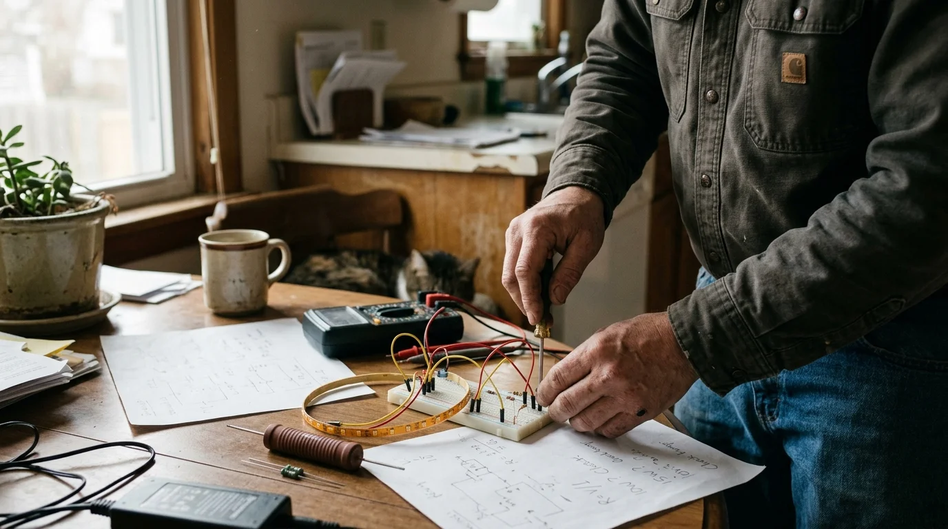
Class 2 Electrical Sizing and Resistor Wattage Configurations
Residential low-voltage wiring hidden behind baseboards or within wall chases must satisfy National Electrical Code (NEC) Article 725. This article sets Class 2 circuit power limitations at a maximum of 60V DC and 100 VA per driver output.
Limiting electrical channels to 100 watts effectively mitigates fire risks and eliminates shock hazards within enclosed cavities. Operating continuous 24V DC baseboard runs well below this threshold ensures long-term safety.
Most commercial smart dimmers use pulse-width modulation (PWM) to lower brightness. However, low-cost dimmers operate at switching frequencies below 400 Hz, producing subtle stroboscopic flicker at sub-5% duty cycles.
Ensure your smart LED dimming modules switch at frequencies exceeding 1,000 Hz, with 4,000 Hz preferred. This compliant range satisfies IEEE 1789 standards and avoids neurological fatigue during late-night waking hours.
Smart controllers often struggle to maintain stability at duty cycles under 1 percent. The internal switching transistors may fail to latch reliably, causing faint flutter or erratic ghosting.
Installing an inline metal-film ballast resistor or bleeder circuit across the driver output terminals stabilizes low-amperage operation. This hardware pull-down establishes a consistent minimum load floor for the controller.
To size a bleeder resistor, calculate the power dissipation based on continuous 24-volt potential. Use Ohm’s Law and the standard power equation to determine necessary resistance and component wattage ratings.
- Target Bleeder Current: 15 milliamps (0.015 A) to hold the smart controller output stage stable.
- Resistance Calculation: R = V / I = 24V / 0.015A = 1,600 Ohms (use a standard 1.5 kΩ or 1.6 kΩ value).
- Thermal Wattage Loss: P = V × I = 24V × 0.015A = 0.36 Watts.
- Resistor Power Rating: Select a 1-watt or 2-watt rated metal-film resistor to provide a 3× safety margin and prevent overheating.
Solder your bleeder resistor inside a ventilated metal junction box adjacent to the Class 2 driver. Never leave uninsulated resistor leads resting against timber framing or baseboard PVC.
Use 18 AWG stranded, oxygen-free copper wire for secondary DC distributions up to 30 feet. This wire gauge keeps continuous voltage drop below 1.2 percent across typical apartment hallway lengths.
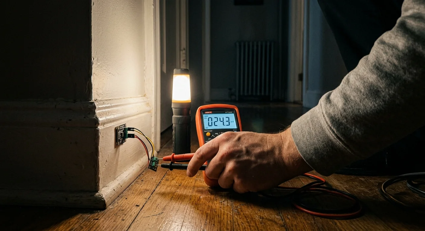
Sensor Calibration: Low-Lux Millivolt Thresholds and Placement
Standard passive infrared (PIR) sensors struggle in split-schedule apartments. Wide 120-degree detection lenses pick up partner movements from inside bedrooms, accidentally triggering hallway lighting.
Mount narrow-beam PIR or millimeter-wave (mmWave) radar sensors 3 to 4 inches above the floor. Position them beneath the direct line of sight of bedroom doorways to isolate hallway foot traffic.
Equip your microcontroller or smart sensor hub with a photodiode to monitor true ambient light levels. Sensors like the TEMT6000 output an analog signal between 0 and 3,300 millivolts corresponding to ambient brightness.
A completely dark corridor generates an analog sensor signal between 0 and 50 millivolts. Ambient light spill from an open living room window pushes that reading past 400 millivolts.
- Mount the ambient lux photodiode flat against the baseboard facing away from direct fixture output.
- Record the quiescent voltage output at midnight with all apartment fixtures switched off (baseline lux).
- Set your automation trigger threshold to active only when ambient voltage drops below 85 millivolt limits.
- Install 15-degree lateral plastic baffles over the sensor casing to narrow its horizontal detection window.
- Confirm that door openings from the primary bedroom do not sweep across the motion detection beam.
Millimeter-wave radar modules allow you to configure precise digital detection zones. You can map sensor boundaries to stop within 6 inches of the bedroom door threshold.
This software boundary ignores movements inside the bedroom while detecting your first step into the hall. You navigate smoothly without disturbing anyone resting inside.
Calibrating these analog thresholds ensures the 2200K strip activates only during true nocturnal darkness. Morning daylight will not trigger unnecessary illumination cycles.
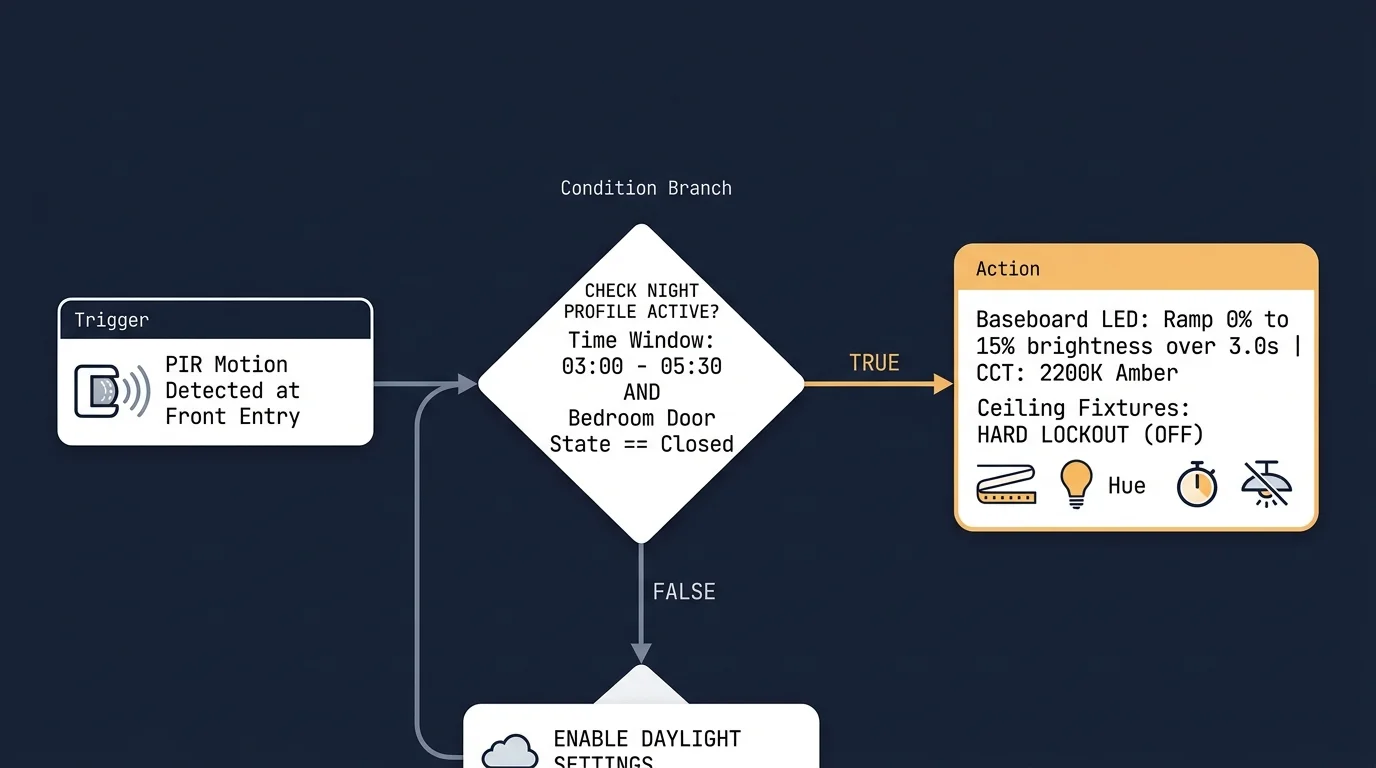
Automation Logic and Controller Scripts for Split-Schedule Homes
Reliable night-shift lighting requires deterministic local automation logic. Relying on cloud-based processing introduces inconsistent delays that leave you waiting in a dark hallway.
Your automation platform should monitor home states using local network protocols. Establish an isolated night-shift logic routine that overrides standard evening scenes between 01:00 and 07:00.
Check multiple condition layers before firing low-level floor illuminations. Verify time windows, bedroom door contact sensor states, and your partner’s sleep status.
- Condition 1 (Time Boundary): System clock reads between 01:00 and 06:30.
- Condition 2 (Illuminance State): Hallway photodiode output remains strictly below 85 millivolts.
- Condition 3 (Primary Occupancy): Bedroom door contact sensor registers closed, or smart mattress reports asleep.
- Condition 4 (Trigger Event): Low-level baseboard mmWave sensor detects ankle-height entry movement.
Configure your smart dimmer controller to execute a gentle 3-second soft-start ramp curve. Snapping LEDs on instantly shocks dark-adapted eyes, causing pupil constriction and visual disorientation.
Set the maximum brightness ceiling between 1.5% and 3.5% of total PWM duty cycle. This low drive current produces roughly 2 to 4 photopic lux along the floor surface.
Establish a strict 90-second countdown timer that resets with every detected footstep. If no further movement occurs, slowly fade the diodes back to zero over 10 seconds.
Program a manual bypass into the automation script. Pressing an auxiliary wall switch three times can restore 100% brightness during daytime cleaning or emergency situations.
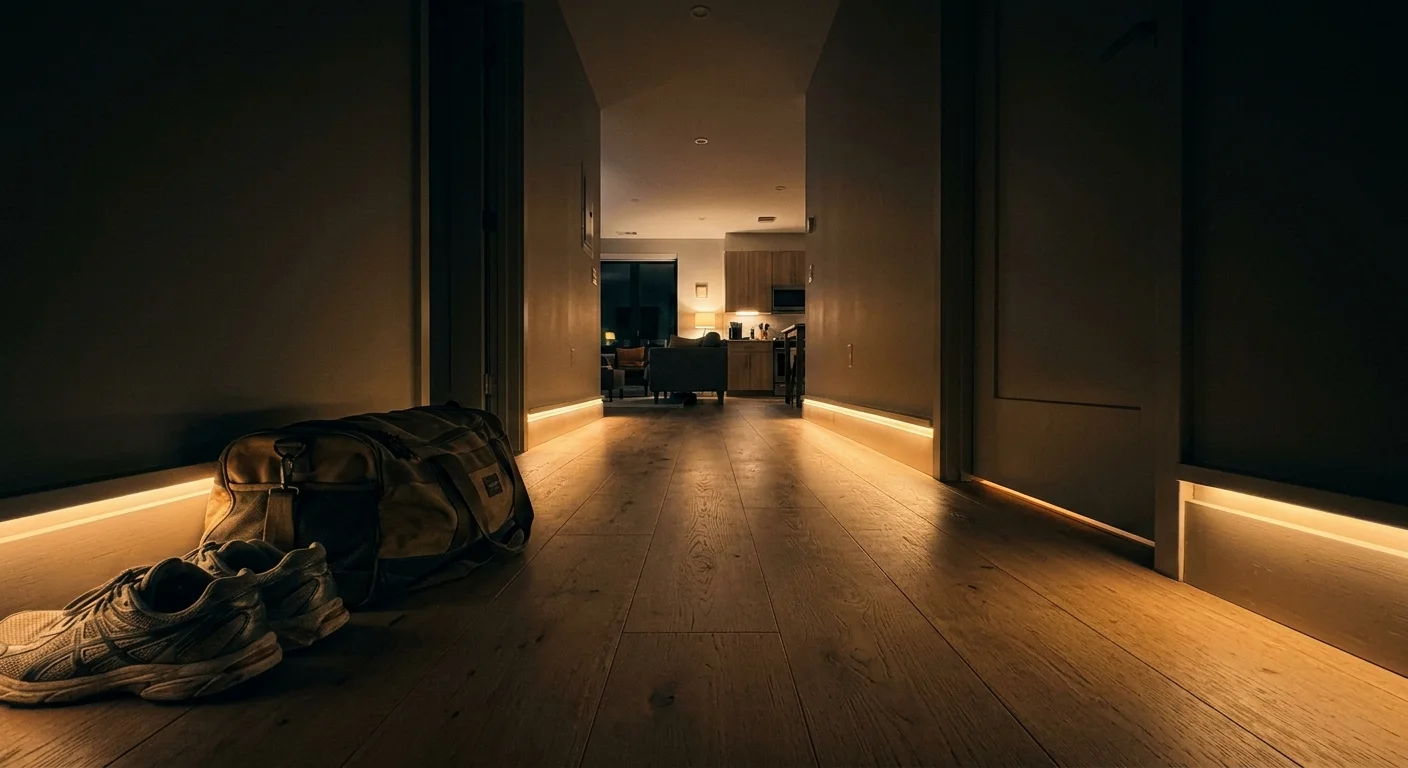
A Worked Implementation: 800-Square-Foot Hallway Retrofit
Consider an 800-square-foot apartment corridor measuring 16 feet long by 3.5 feet wide. The hallway connects an ICU nurse’s entryway to the bathroom and a bedroom housing an office worker.
The design goal requires under-baseboard guidance that limits mattress-level illumination to under 0.1 photopic lux (under 0.03 m-EDI). Total light spill must stay below international circadian disruption thresholds.
The installation uses a 5-meter reel of 24V COB 2200K strip running 480 diodes per meter ($26). Aluminum 45-degree corner channels with frosted diffusers cost $34 across three 2-meter lengths.
A Mean Well XLG-75-24-A Class 2 driver ($32) powers the system. A Zigbee 3.0 PWM dimmer ($22) and an ESP32-based ankle sensor module ($14) complete the bill of materials, totaling $128.
- Isolate primary power at the service panel before mounting the Class 2 driver inside the hallway linen closet.
- Cut aluminum extrusions to fit wall segments using a fine-tooth 120-tooth carbide miter blade.
- Fasten the channels directly to the drywall baseboard reveal using countersunk 0.75-inch mounting screws.
- Wipe the internal aluminum surface with 90% isopropyl alcohol to promote secure thermal adhesive bonding.
- Press the 24V 2200K COB strip into the extrusion channel, routing lead lines back to the closet driver.
- Solder a 1.5 kΩ, 2-watt metal-film bleeder resistor across the DC dimmer output channels.
- Snap frosted polycarbonate diffusers into place, angling internal flanges 45 degrees downward toward the floor.
- Mount the ankle-height sensor 3.5 inches above the floor and pair it with your local automation hub.
Commissioning tests confirm the system’s photometric accuracy. At a 2.5% dimmer drive current, the strip draws 0.06 amps at 24V DC, consuming only 1.44 watts.
Floor lux meters register 2.8 photopic lux directly along the center line of the corridor. Readings taken at the bedroom threshold 24 inches above the floor register 0.04 photopic lux.
Calculated melanopic lux at the sleeping partner’s pillow drops below 0.015 m-EDI. The installation keeps light far below the 1-lux threshold, ensuring zero sleep disruptions.
Frequently Asked Questions
Why choose 2200K over standard 2700K warm white tape?
Diodes rated at 2200K emit far less energy in the 480-nanometer blue-green spectrum. This lower biological impact suppresses substantially less melatonin, preserving your sleep drive after completing a night shift.
Will frosted diffusers alone prevent floor hotspots?
Frosted covers help, but traditional low-density SMD LED strips still reflect visible dots off glossy floors. Using Chip-on-Board (COB) strips with 480 or more diodes per meter creates a smooth, continuous line of light.
Can I install these low-voltage ribbons under existing baseboards without cutting drywall?
Surface-mounted asymmetric deflector profiles adhere directly to the bottom edge of standard baseboards using heavy-duty adhesive tape. You can route thin 18 AWG Class 2 wire beneath carpet edges or around baseboard corners.
How do I stop my cat from triggering the ankle-height motion sensors?
Targeted millimeter-wave radar modules allow you to configure minimum object mass and motion reflection thresholds. This processing logic filters out small pets while reliably detecting walking human legs.
Disclaimer: This article is for informational purposes only. Smart home devices involve electrical connections and data privacy. Always follow manufacturer instructions for installation. For complex wiring or HVAC work, consult a licensed professional.