You can eliminate the irritating transformer buzz and LED flicker in your 12V landscape lighting immediately without replacing your outdoor fixture run. That loud 120 Hz hum starts the moment a solid-state smart switch sends chopped phase-angle power into an inductive magnetic core.
Outdoor transformers experience temperature-induced electrical variations similar to cold-start smart shop lights when winter weather shifts driver thresholds.
Most smart switches leak low-voltage standby current that causes secondary-side LED drivers to strobe erratically in low-wattage setups.
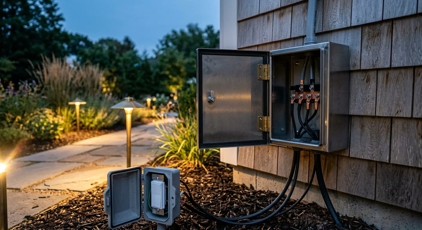
Unlike generic advice suggesting you replace your outdoor fixtures, wiring a dedicated 10W to 25W dummy load bypass across the 120V primary terminals dampens coil magnetostriction and stabilizes the holding current.
The Physics of Smart Switch Transformer Buzz: Magnetostriction and Phase Chopping
Smart dimmers regulate light levels by slicing the alternating current (AC) waveform. This process, known as phase-angle chopping, creates abrupt voltage rises that disrupt standard inductive coils.
These acoustic resonance problems are especially disruptive on projects like cascading smart stair lighting where transformers are housed directly beneath interior living areas.
Standard household utility power delivers a clean, smooth 60 Hz sine wave. Standard mechanical switches pass this entire sine wave directly through the transformer coils without interruption.
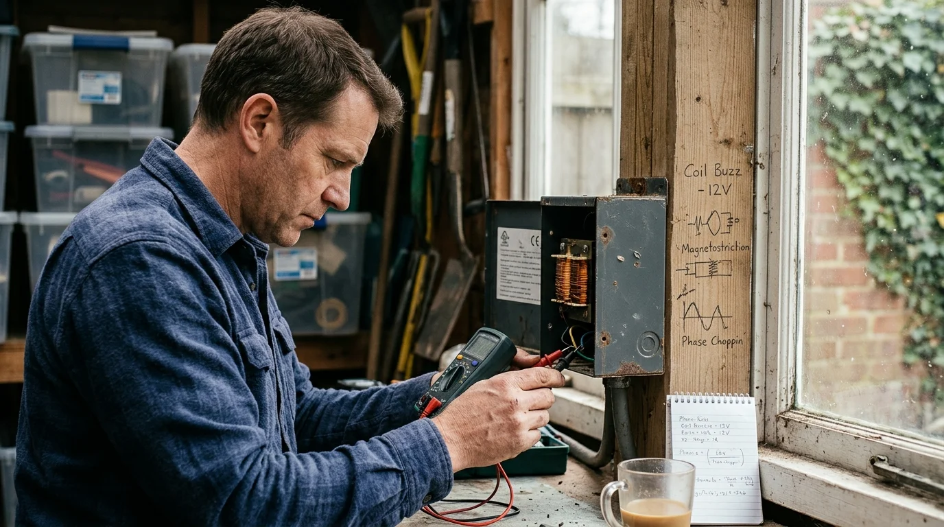
When an iron or silicon-steel transformer core encounters alternating magnetic fields, the physical metal core expands and contracts microscopically. Electrical engineers refer to this dimensional change as magnetostriction.
Under a clean sine wave, magnetostriction produces a faint, low-frequency hum at 120 Hz. Because the transitions are smooth, the acoustic volume remains almost completely inaudible outside the chassis enclosure.
“Inductive loads resist changes in current, converting electrical phase distortion directly into mechanical noise through acoustic resonance.”
Forward-phase smart dimmers use components called TRIACs or silicon-controlled rectifiers (SCRs). These devices delay electrical turn-on until midway through each half-cycle, instantly slamming full line voltage into the core.
This near-vertical voltage edge contains high-frequency harmonic energy spanning 500 Hz to 20 kHz. These harmonics force the laminated steel sheets inside the transformer to vibrate against one another violently.
The resulting acoustic disturbance is the loud smart switch transformer buzz you hear radiating from the housing. Over time, these harmonic vibrations can degrade coil insulation and loosen transformer mounting hardware.
Magnetic vs. Electronic Transformers: Load Impedance and Inrush Current
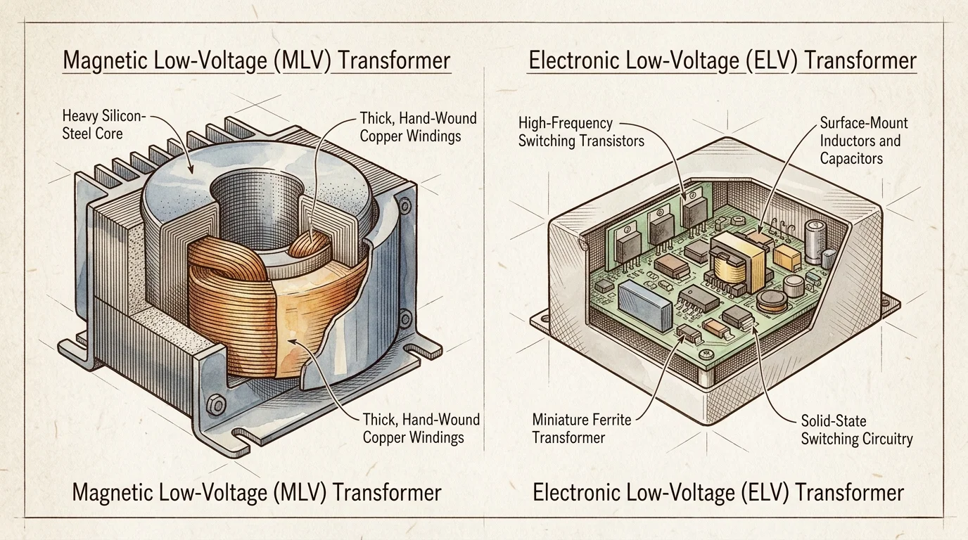
Landscape lighting transformers fall into two engineering categories: magnetic low-voltage (MLV) and electronic low-voltage (ELV). Treating them identically during smart home automation installations causes equipment failure.
Similar minimum-load issues frequently occur when integrating low-wattage low-voltage deck accents or step lights into older multi-tap transformers.
Magnetic low-voltage transformers use heavy laminated steel cores wound with copper wire. They are inductive loads that inherently resist rapid changes in current flow.
Electronic low-voltage units use high-frequency solid-state inverter circuits to step 120V line power down to 12V. They present a capacitive load profile to your wall controls.
Older landscape transformers were engineered specifically for power-hungry incandescent and halogen lamps. A typical multi-tap outdoor transformer was designed to run between 100W and 600W continuously.
When you retrofit your fixtures with modern 3W or 5W LEDs, the total electrical draw drops dramatically. A run of eight pathway lights might draw only 24W from a 300W power pack.
This massive reduction introduces severe load impedance mismatches. Magnetic transformers require a minimum magnetic flux density inside the core to maintain voltage stability.
Without sufficient load current, the transformer operates in an unstable region of its saturation curve. According to testing guidelines from PCMag Smart Home experts, pairing smart controls with heavily underloaded inductive circuits causes significant control malfunction.
- Laminated Core MLV: Uses stacked steel plates; highly prone to 120 Hz acoustic buzzing under chopped phase angles.
- Toroidal Core MLV: Uses a donut-shaped magnetic core; produces lower baseline noise but exhibits high inrush current that trips smart relays.
- Solid-State ELV: Uses internal high-frequency switching; incompatible with forward-phase dimmers and requires dedicated reverse-phase trailing-edge controls.

Why Smart Dimmers Cause 12V Low Voltage Flicker
The dreaded 12V low voltage flicker smart switch issue stems from how smart electronics harvest their operational power. Smart switches must power their internal Wi-Fi, Z-Wave, or Zigbee radios around the clock.
If your landscape runs share electrical feeds with high-draw fixtures or outdoor smart floodlights, sudden current shifts can trigger further intermittent strobing.
In homes where the electrical box lacks a neutral wire, the smart switch pulls phantom power right through the load. This tiny trickle of standby current travels continuously through the transformer primary coil.
Halogen bulbs burned off this trickle current as imperceptible heat without illuminating. Modern LED fixtures cannot absorb this leakage current safely.
Each LED landscape fixture houses its own internal miniature switch-mode driver and rectifier circuit. These internal drivers contain small smoothing capacitors that store incoming electrical charge.
Standby leakage current slowly trickles into these fixture capacitors over several seconds. Once the voltage threshold reaches the LED driver trigger point, the bulb discharges the capacitor in a rapid flash.
The capacitor depletes instantly, the light turns off, and the cycle repeats endlessly. This causes continuous strobe-like flashing when the switch is nominally turned off.
A second flicker mechanism occurs while the lights are fully operational. Forward-phase dimmers require a continuous electrical holding current to keep their internal semiconductor switches conductive.
When the dimmer throttles down to lower levels, low-wattage LEDs fail to pull enough continuous amperage. The dimmer switch repeatedly cuts out and restarts within fractions of a second, generating visible light strobe.
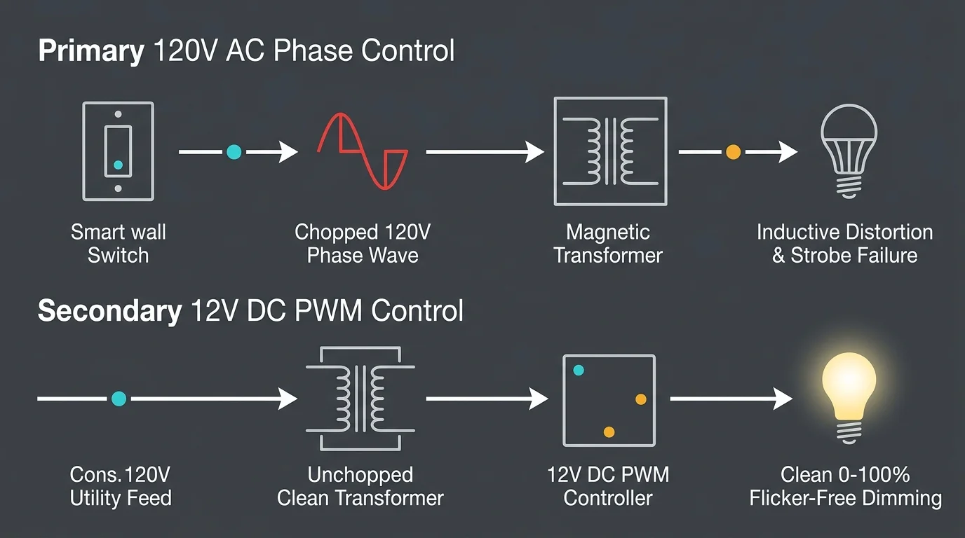
Primary Side vs. Secondary Side Control: Why Chopping 120V Fails Low-Voltage LEDs
Dimmable smart switches are designed to modulate power on the 120V AC primary circuit. This architecture works reliably for standard household incandescent fixtures and line-voltage LED bulbs.
Homeowners managing larger yards can avoid primary-side distortion entirely by establishing isolated smart lighting zones through dedicated secondary DC controllers.
Applying this strategy to landscape lighting forces the chopped 120V waveform through a transformer and secondary rectifiers. By the time that chopped power reaches the LED emitter, the wave shape is severely degraded.
The secondary side of a landscape transformer outputs 12V AC. LED chips, however, require smooth direct current (DC) to emit steady light.
Every quality low-voltage LED bulb contains a bridge rectifier to convert 12V AC into raw DC. It also contains filtering capacitors and a constant-current buck regulator.
When you chop the 120V primary sine wave, the internal transformer winding distorts the phase cuts through magnetic inductance. This delivers a chaotic, jagged electrical signal to the bulb rectifier.
The fixture buck regulator tries desperately to smooth out these missing voltage chunks. As the regulator fights the chopped waveform, you experience severe landscape lighting smart dimmer hum and unstable light levels.
Attempting to dim complex switching electronics using primary-side phase clipping is inherently inefficient. True, flicker-free dimming requires pulse-width modulation (PWM) executed directly on the 12V DC secondary line.

Step-by-Step Engineering Calculation: Sizing Your Dummy Load Bypass Capacitor
To eliminate coil buzz and line chatter, you must provide an electrical escape path for phase spikes. Installing a parallel dummy load bypass stabilizes both the smart switch holding current and inductive voltage spikes.
These same resistive load calculations also resolve ghosting and standby glow when powering weatherproof smart light strips with low-draw external drivers.
Let us work through a concrete electrical engineering scenario. Assume you operate a 150W magnetic core transformer powering six 4W LED pathway fixtures.
Your total active lighting load is only 24W (6 fixtures multiplied by 4W). At 120V line voltage, your nominal system current draw is 0.20A under purely resistive calculations.
However, small LED drivers exhibit a low power factor, typically around 0.60. When dimmed to a 25% target level, the real operating current often drops below 0.03A (30mA).
Most solid-state smart dimmers require a continuous holding current of at least 40mA to 50mA to stay latched. The system falls below this operational threshold, initiating heavy coil buzz and strobe flicker.
To restore stability, your circuit requires an auxiliary bypass that pulls an additional 10W to 15W of steady load across the 120V primary. You calculate the required electrical resistance using Ohm’s Law.
Start with the fundamental power formula: Power equals Voltage squared divided by Resistance (P = V² / R). Rearranging this formula yields Resistance equals Voltage squared divided by Power (R = V² / P).
Plugging in 120V line power and a 15W target dummy dissipation: 120 multiplied by 120 equals 14,400. Divide 14,400 by 15W to calculate your required resistance of 960 Ohms.
A standard 1,000 Ohm (1kΩ) power resistor satisfies this electrical target. When selecting this resistor, you must double the physical power rating to prevent thermal burnout.
A 15W continuous load requires a 25W or 50W wirewound aluminum-housed resistor. Alternatively, you can install an AC-rated snubber capacitor designed to absorb high-frequency harmonics without generating continuous heat.
For an AC capacitive bypass snubber, calculate target capacitive reactance (Xc) using the line frequency of 60 Hz. The standard formula is: Xc = 1 / (2 * π * f * C).
Installing an electrical snubber rated between 0.47µF and 1.0µF provides an ideal low-impedance shunt for 2 kHz to 10 kHz harmonic frequencies. This drains the destructive harmonics causing magnetostriction while leaving the 60 Hz primary power intact.
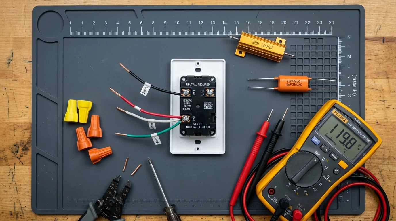
Hardware Comparison: Smart Dimmers and Bypass Resistors for 12V Loops
Selecting the right hardware combination prevents hours of troubleshooting in the field. Field reviews from Wirecutter Smart Home evaluations confirm that component compatibility determines whether low-voltage lighting loops buzz.
The table below compares dedicated bypass components and smart control hardware for 12V landscape power supplies.
| Device / Hardware | Component Profile | Continuous Power Dissipation | Minimum Circuit Load | Recommended Application |
|---|---|---|---|---|
| Lutron LUT-MLC | Metalized Film Capacitor Snubber | 0.5W (negligible heat) | 5W equivalent shunt | No-neutral switches; fixes ghosting and mild core buzz |
| Aeotec Bypass Gen5 | Capacitive & Resistive Network | 1.2W internal drain | 8W equivalent shunt | Z-Wave dimmers paired with small 10W-30W LED runs |
| 25W 1kΩ Aluminum Resistor | Pure Resistive Wirewound Load | 14.4W continuous | 15W true load | Underloaded magnetic transformers with severe 120 Hz core hum |
| Lutron Caseta ELV+ (PD-5NE) | Reverse-Phase (Trailing Edge) Dimmer | N/A (Active Controller) | 10W true load (requires neutral) | Electronic low-voltage transformers requiring zero-cross cutoff |
| Shelly RC Snubber | Resistor-Capacitor Series Suppressor | 0.2W passive filter | Suppresses inductive back-EMF | Smart relays controlling magnetic transformer on/off circuits |
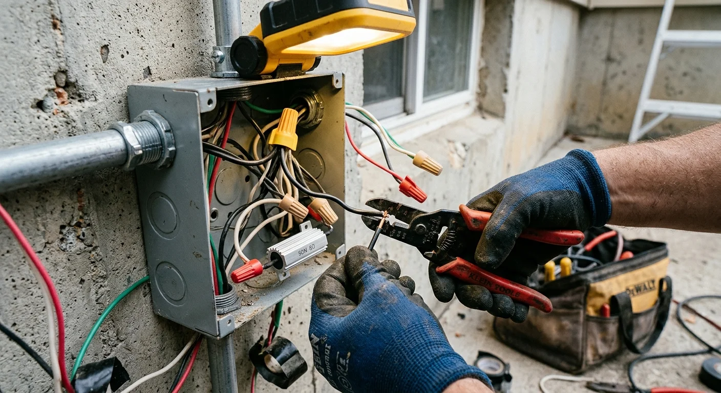
Step-by-Step Installation: Wiring a Snubber or Dummy Load on the 120V Primary Line
Follow these precise steps to install your calculated bypass device and silence magnetic transformer buzz. Always prioritize safety when modifying line-voltage components.
- Disconnect electrical power at the main service panel circuit breaker, and lock out the breaker box.
- Verify the circuit is completely dead using a calibrated non-contact voltage tester or digital multimeter set to AC volts.
- Open the line-voltage wiring compartment of your outdoor landscape transformer enclosure.
- Identify the switched hot lead running from your smart switch and the incoming system neutral conductor.
- Wire the bypass device in parallel across the switched hot and neutral connections using exterior-rated wire connectors.
- Ensure you do not wire the bypass device in series; wiring it in series will choke voltage to the transformer.
- If using an aluminum power resistor, mount the metal casing to an exterior metal junction box surface to dissipate heat safely.
- Tuck all spliced conductors neatly inside the enclosure, reattach the weather gasket, and secure the access panel.
- Restore circuit breaker power and observe the landscape transformer operation across the full smart switch dimming range.
- Access your smart dimmer software application and configure the low-end trim setting to cut off power before holding current drops below 30%.
Setting the low-end trim in your smart home mobile app ensures the dimmer never throttles down into the unstable dropout zone. Most outdoor landscape LEDs display zero visible dimming difference between 0% and 25% primary phase chop.
Locking your dimmer floor at 30% eliminates dropouts without sacrificing practical night-time ambiance. This software adjustment works alongside the hardware bypass to guarantee silent performance.
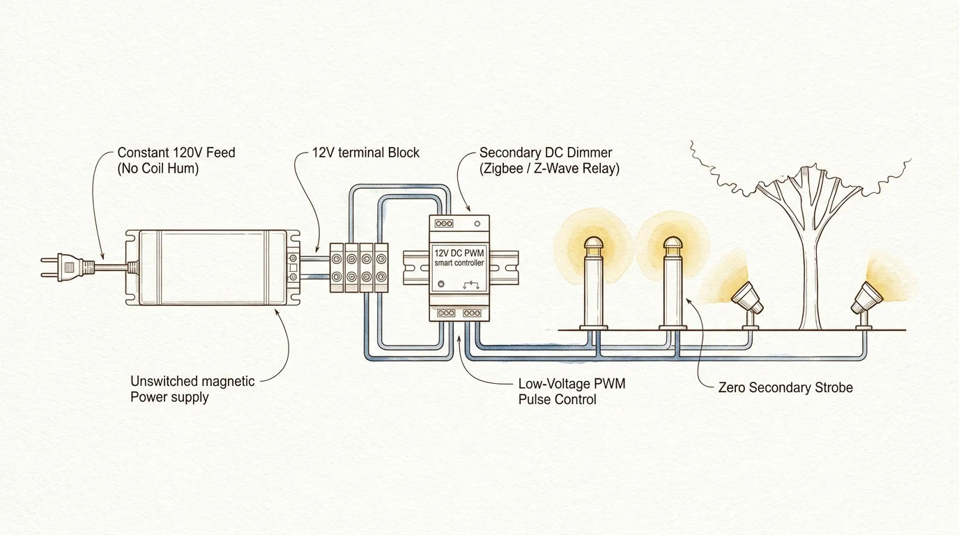
Secondary Side Automation Alternatives: 12V DC PWM Controllers and Relays
If you want flawless dimming without secondary coil buzz, abandon 120V primary-side dimming entirely. The modern engineering standard separates high-voltage on/off switching from low-voltage dimming regulation.
Under this architecture, you install a standard on/off smart relay (such as a Shelly Plus 1PM or Zooz ZEN51) on the 120V primary line. Relays do not chop the AC sine wave, completely preventing magnetostriction and acoustic buzz.
Your magnetic transformer receives pristine, undistorted 120V line power every time the smart switch activates. This eliminates hum at the outdoor power station completely.
To control light brightness, you transition the secondary side of your transformer from raw 12V AC to steady 12V DC. You achieve this by installing a bridge rectifier and a 12V DC constant-voltage LED driver.
Once you establish a clean 12V DC bus line, you wire an inline pulse-width modulation (PWM) smart controller directly before the outdoor fixtures. Zigbee, Z-Wave, and Wi-Fi low-voltage PWM modules operate seamlessly on 12V DC lines.
- Constant Sine Wave: The transformer receives full 60 Hz line power, keeping core noise below ambient outdoor sound levels.
- Precise 0.1% Dimming: PWM secondary controllers adjust light intensity by flashing the DC voltage at kilohertz speeds invisible to human eyes.
- Color Temperature Control: DC secondary wiring allows you to automate tunable white and RGB landscape accents using common smart home platforms.
- Extended Driver Longevity: Operating LED fixtures on clean direct current keeps internal components cool, significantly extending hardware lifespans.
You can automate your primary smart switch using sunrise and sunset routines inside your home automation hub. For example, command the primary relay to energize at dusk, while setting the secondary PWM controller to 70% brightness.
At 11:00 PM, trigger an automated scene that ramps the pathway lights down to 20% intensity for rest-of-night security. This configuration delivers full smart home flexibility without a single decibel of transformer noise.
Frequently Asked Questions
Can transformer coil buzz damage my outdoor LED landscape fixtures?
Yes, persistent coil buzz generated by phase-cut dimmers can damage your lighting fixtures over time. The high-frequency harmonic voltage spikes that produce acoustic vibrations stress the miniature bridge rectifiers and capacitors inside LED bulbs, drastically shortening their operating lifespan.
Why does my landscape transformer only buzz when the lights are dimmed low?
As you dim the lights lower, the phase-angle cut on the 120V sine wave becomes steeper and more abrupt. This aggressive waveform chopping produces severe harmonic distortion while simultaneously dropping circuit current below the smart dimmer’s required holding threshold.
Can I install a dummy load resistor inside the outdoor transformer housing?
Only install passive snubber capacitors inside compact outdoor transformer compartments. True power resistors dissipate electrical energy as continuous heat; they must be securely heat-sinked to an external metal junction box away from combustible materials and delicate low-voltage insulation.
What is the difference between a snubber capacitor and a dummy load resistor?
A dummy load resistor burns off power continuously across all frequencies to pull operating amperage through the switch. A snubber capacitor acts as a frequency-sensitive filter, draining only the high-frequency voltage spikes that cause transformer hum while consuming almost zero real power.
Disclaimer: This article is for informational purposes only. Smart home devices involve electrical connections and data privacy. Always follow manufacturer instructions for installation. For complex wiring or HVAC work, consult a licensed professional.