
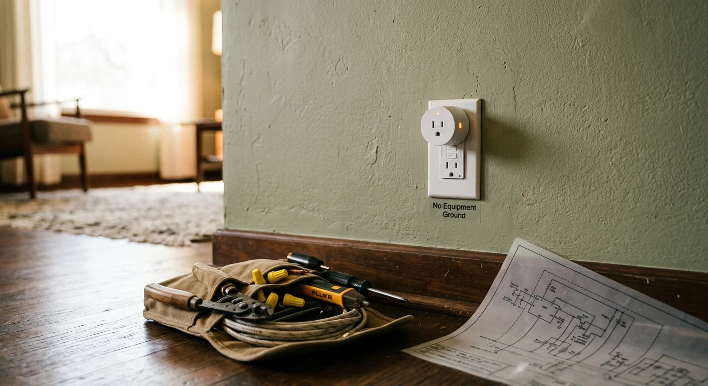
You can install modern smart plugs and automated switches in your 1950s ranch home without spending $15,000 on a full electrical rewire. By pairing National Electrical Code (NEC) 406.4(D)(2) GFCI protection with load-side bypass capacitors, you safely unlock smart control on legacy two-wire systems.
If you are just beginning to evaluate connected hardware, our guide on smart home basics for beginners outlines essential platform concepts before you touch any wiring.
Most automation tutorials assume your wall boxes contain modern neutral conductors and continuous equipment ground paths. This setup walkthrough shows how to solve both wiring deficits simultaneously while staying fully code-compliant.
You will establish shock-safe smart power outlets and flicker-free smart switches throughout your mid-century living space today.

Why 1950s Branch Circuits Reject Standard Smart Hardware
Homes constructed during the post-war building boom of the 1950s relied on electrical standards drastically different from modern requirements. The National Electrical Code did not mandate equipment grounding conductors for general branch circuits until 1962.
Unlike modern construction projects where pre-drywall smart wiring upgrades ensure deep boxes and neutral wires everywhere, retrofitting vintage circuits requires working within strict physical and electrical limits.
Before purchasing new hardware, take the time to test if your home is ready for smart devices by inspecting your existing line feeds and panel configuration.
Your mid-century home likely contains original two-wire branch circuits consisting only of a hot conductor and a neutral conductor. These circuits terminate in classic two-prong ungrounded receptacles that cannot mechanically accept three-prong smart device plugs.
Wall switch enclosures in 1950s homes present an equally frustrating obstacle for automation upgrades. Builders routed power directly to the ceiling luminaire first, dropping down a two-conductor “switch loop” to control the light.
This legacy switch loop design brings only incoming line voltage and switched load voltage into the switch wall box. It leaves out the continuous neutral conductor that modern smart switches require to power their internal Wi-Fi or Zigbee radios.
The NEC did not require a neutral conductor in switch enclosures until adopting Section 404.2(C) in 2011. Consequently, standard smart home switches shut down completely the moment you turn the connected light fixture off.
Physical space inside your 1950s wall boxes creates a third major hurdle. Mid-century builders used shallow steel handy boxes or narrow metal gem boxes with volumes under 14 cubic inches.
Squeezing bulky modern connected hardware into these compact enclosures frequently violates box-fill limits established by NEC Section 314.16. Forcing large components into tiny metal boxes risks damaging vintage cloth-insulated conductor wiring.

The NEC 406.4(D)(2) Code Strategy for Ungrounded Smart Plugs
You do not need to tear through your plaster walls to add modern smart plugs ungrounded outlets can safely host. The National Electrical Code offers a direct legal remedy in NEC Section 406.4(D)(2).
Once an ungrounded outlet is properly protected, you can safely use it for everyday automation routines like automating your coffee maker with a smart plug.
This code section permits homeowners to replace an existing two-prong ungrounded receptacle with a Ground Fault Circuit Interrupter (GFCI) receptacle. You can also replace downstream two-prong outlets with standard three-prong grounding-type receptacles when protected by an upstream GFCI.
A GFCI device monitors the balance of electrical current flowing between the hot and neutral conductors. If it detects a leakage current between 4 milliamperes (mA) and 6 mA, it severs power in less than 25 milliseconds.
This rapid cutoff protects human life from lethal ventricular fibrillation during an electrical fault. The GFCI accomplishes this life-saving detection entirely without needing an equipment ground wire.
Safety in an ungrounded circuit relies on rapid current interruption rather than physical earth grounding paths.
To remain compliant with NEC 406.4(D)(2)(b) and 406.4(D)(2)(c), you must apply specific physical labels provided in the outlet box:
- The GFCI receptacle itself must display a visible label reading “No Equipment Ground”.
- Any downstream three-prong receptacles powered from the GFCI load terminals must display two labels: “GFCI Protected” and “No Equipment Ground”.
- You can apply these adhesive labels directly onto the receptacle face or onto the exterior wall plate.
- You must ensure the labels remain clearly legible after completing final device installation.
Once you install this GFCI boundary, you can safely insert modern smart plugs into these newly created three-prong receptacles. This configuration creates a legally compliant foundation for your smart home no ground wire environment.
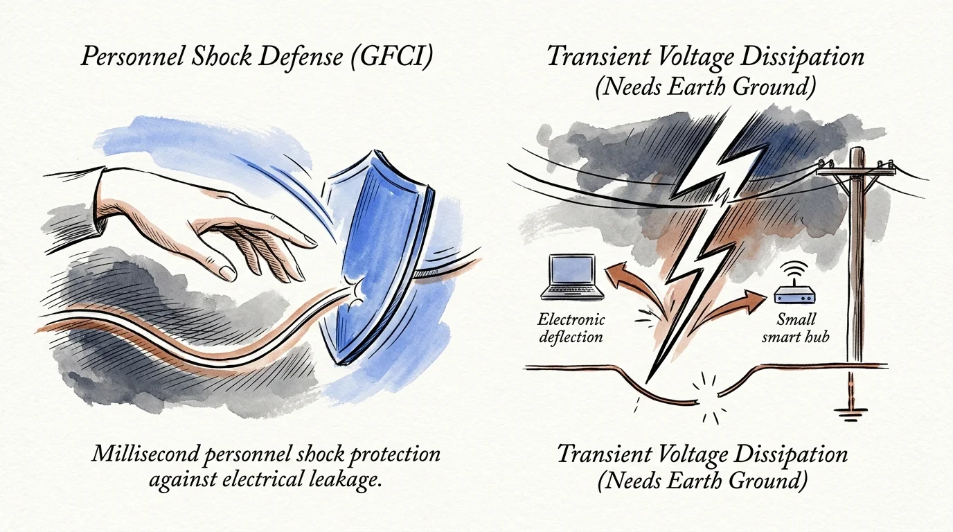
Ground Faults vs Surge Protection: The Two-Wire Trade-Off
While a GFCI installation ensures personal safety, you must understand the difference between shock protection and surge protection. A GFCI device protects humans; it does not protect sensitive electronic circuitry from transient voltage spikes.
Protecting your gear from line transients is only one aspect of grid readiness; review our smart home power outage survival guide to safeguard your automations during prolonged blackouts.
Standard consumer surge protector strips rely on internal components called Metal Oxide Varistors (MOVs). These MOVs clamp excessive voltage surges and divert that destructive energy directly into the equipment ground conductor.
On an ungrounded two-wire circuit, an MOV cannot dump common-mode electrical surges away from your electronics. The surge energy has nowhere to go because an earth ground conductor does not exist in the wall box.
Consequently, high-end electronics like smart televisions, audio receivers, and smart hubs remain vulnerable to power spikes. The GFCI protects your body from electrocution if an internal short occurs, but it cannot prevent lightning transients from frying internal microchips.
If you need true hardware surge suppression in a 1950s property, consider these practical options:
- Install a Type 2 Whole-House Surge Protective Device (SPD) at your main breaker panel where true earth grounding exists.
- Use series-mode surge suppressors that dissipate surge energy as heat across inductors rather than diverting voltage to ground.
- Hire a licensed electrician to run a dedicated Equipment Grounding Conductor under NEC 250.130(C) back to your service panel.
Understanding this distinction prevents costly equipment failures. Treat your GFCI receptacles as life-safety devices while relying on panel-level protection for sensitive automation controllers.

No-Neutral Smart Lighting: Switch Loops and Bypass Capacitors
Automating your ceiling lights without running new Romex cable requires a specialized two prong outlet smart switch strategy. Modern no-neutral smart dimmers power their internal microprocessors by siphoning a tiny leakage current through the lighting circuit continuously.
You can use these same no-neutral wiring methods on outdoor circuits when learning how to automate your porch lights for safety.
If your vintage room lacks switch wall boxes altogether, you can convert pull-chain ceiling fixtures to smart switches using compact in-canopy controllers.
When the light switch sits in the “off” position, a fraction of a milliampere continues flowing through the load. With vintage incandescent bulbs, this tiny standby current went unnoticed because heavy tungsten filaments require significant power to glow.
Modern LED bulbs operate at extremely high electrical efficiency. That tiny leakage current charges the capacitors inside the LED bulb driver circuit, creating undesirable side effects.
Your ceiling fixture might flicker violently while turned on. Alternatively, the bulbs may emit a faint, ghostly glow long after you flip the switch to the off position.
Most no-neutral dimmers require a minimum operating load between 15 watts and 25 watts. A single modern 8-watt LED bulb falls well below this operational threshold.
According to analysis from Wirecutter’s smart home coverage, the Lutron Caséta platform remains the most reliable option for switches lacking a neutral wire. Lutron solves the leakage dilemma through an accessory known as a load-side bypass capacitor.
The bypass capacitor (such as the Lutron LUT-MLC or Aeotec Bypass) wires in parallel with your light fixture inside the ceiling electrical box. It connects directly between the switched hot wire and the neutral wire feeding the luminaire.
The capacitor acts as an electrical sponge for alternating current. It absorbs the switch radio’s standby trickle current while providing high resistance to normal operational voltage.
This diversion prevents the LED driver capacitors from charging while the switch rests in the off position. Your LEDs remain completely dark when powered down, and your smart switch maintains constant connectivity to your home network.
Selecting hardware that conforms to the Matter smart home standard or established wireless protocols ensures your no-neutral switches communicate smoothly with your favorite voice assistants.
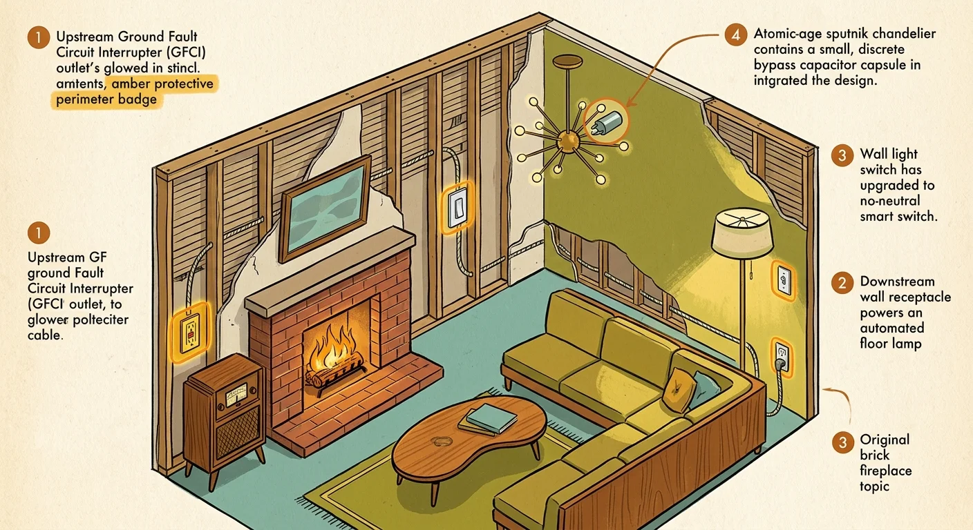
Worked Example: Retrofitting a 1950s Living Room Circuit
Consider a typical 1950s ranch living room powered by a single 15-amp branch circuit wired with two-conductor cloth-sheathed cable. The room contains six two-prong wall outlets and a single ceiling fixture controlled by a two-wire wall switch loop.
Keeping retrofits affordable mirrors the strategies in our guide to building a smart home on a budget under $100, proving you do not need expensive overhauls to modernize your space.
Using smart wall switches rather than smart bulbs alone maintains familiar wall control, fulfilling the key rule in our physical-fallback blueprint to keep living spaces frustration-free for everyone.
A full electrical rewire to bring modern three-wire cables to every outlet box averages between $2,000 and $3,500 for that single room. Plaster repair and repaint costs add another $1,000 to the total bill.
Instead, we implement our code-compliant GFCI and bypass retrofit plan. Here is the exact bill of materials required to convert this living room into an automated space:
- One Leviton GFNT1-W 15-Amp Tamper-Resistant GFCI Receptacle: $18.50
- Five Leviton T5320-W 15-Amp Tamper-Resistant Three-Prong Receptacles: $14.25 total ($2.85 each)
- One Lutron Caséta PD-6WCL No-Neutral Wireless In-Wall Dimmer: $59.95
- One Lutron LUT-MLC Minimum Load Bypass Capacitor: $14.50
- One Kasa Smart Wi-Fi Plug Mini (HS103P2 2-Pack) for floor lamps: $19.99
- One pack of pre-printed NEC electrical outlet warning labels: $4.95
The total hardware expenditure equals $132.14, delivering massive savings compared to structural electrical trenching. The entire retrofit process takes approximately 3.5 hours of focused, methodical labor.
We trace the branch circuit to locate the first receptacle box fed directly from the main breaker panel. We remove the vintage two-prong outlet and install the Leviton GFNT1 GFCI in its place.
The incoming two-wire feed connects to the LINE terminals of the GFCI. The outgoing two-wire cable feeding the remaining five outlets connects to the GFCI LOAD terminals.
We affix a “No Equipment Ground” sticker to the GFCI faceplate. We then replace the five downstream two-prong outlets with standard three-prong outlets, marking each with both “GFCI Protected” and “No Equipment Ground” stickers.
Next, we replace the legacy wall switch with the Lutron Caséta PD-6WCL dimmer. Because no ground wire exists in the metal switch box, manufacturer instructions direct us to cap the switch green ground lead using an insulated wire nut.
Finally, we drop the ceiling fixture canopy and wire the LUT-MLC capacitor across the fixture black and white wire leads. The smart dimmer immediately controls the LED ceiling lights without ghosting, and the smart plugs operate safely in the protected wall receptacles.

Hardware Specifications and Compatibility Breakdown
Selecting the right smart switch requires matching the device specifications to your home physical constraints. The table below compares top no-neutral smart switches and dimmers suitable for 1950s wall box conversions.
| Device Model | Wireless Protocol | Minimum Load Rating | Bypass Capacitor Included? | Ground Wire Requirement | Shallow Box Friendly |
|---|---|---|---|---|---|
| Lutron Caséta PD-6WCL | Clear Connect (434 MHz) | 25W (Incandescent) / 1 Bulb (LED) | Sold Separately (LUT-MLC) | Optional (Cap if missing) | Yes (1.18 inches deep) |
| Leviton Decora DN6HD | Local RF to MLWSB 2.4 GHz Wi-Fi Bridge (sold separately) | 25W (LED) | Not required / Not included (No MLC bypass) | Not Required | Moderate (1.35 inches deep) |
| Sonoff ZBMINIL2 Extreme | Zigbee 3.0 | 3W (LED) | No Bypass Needed | Not Required | Conditional (0.72 in / 18.4 mm deep; verify NEC 314.16 box-fill volume and avoid enclosed shallow steel handy boxes that block Zigbee RF) |
| Inovelli Blue Series 2-in-1 (VZM31-SN) | Zigbee 3.0 (Matter-over-Thread requires Inovelli White Series VTM31-SN) | 25W without bypass / 5W with bypass | Sold Separately | Optional (Programmable) | Moderate (1.2 inches deep) |
The Sonoff ZBMINIL2 micro-relay can tuck behind a mechanical switch to preserve original toggle plates while adding Zigbee control, provided you verify NEC 314.16 box-fill volume and avoid enclosed shallow steel boxes that attenuate 2.4 GHz Zigbee RF.
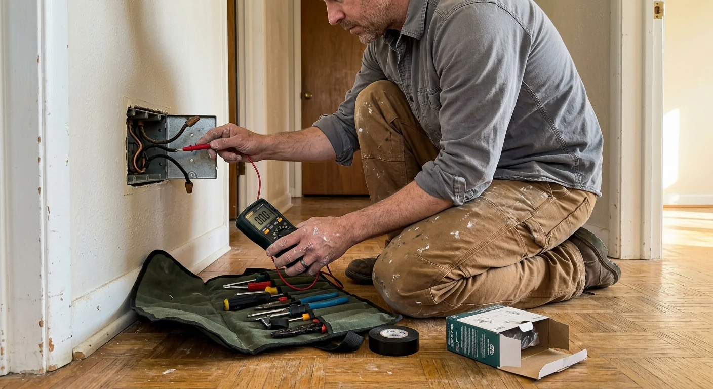
Step-by-Step Installation: Safe Smart Upgrades Without a Rewire
Follow these progressive steps to upgrade your 1950s circuits while maintaining rigorous electrical code compliance. Always adhere to strict safety protocols when working inside electrical enclosures.
-
Isolate Electrical Power at the Panel:
De-energize the target circuit at your main breaker panel. Verify the absence of voltage at the outlet using a calibrated non-contact voltage tester before touching any conductors. -
Identify the First Receptacle in the Branch Circuit:
Open your outlet boxes, disconnect the conductors, and cap every bare conductor end individually with an insulated wire nut before restoring power at the breaker. Use a non-contact voltage tester to identify which box receives line voltage directly from the panel, then turn the breaker off and verify all wires are dead before touching any conductors. Follow manufacturer wiring diagrams and local code, and hire a licensed electrician if you find aluminum or knob-and-tube wiring or are unsure at any step. -
Install the Upstream GFCI Device:
Connect incoming hot and neutral wires to the LINE screw terminals of your new GFCI receptacle. Connect outgoing branch conductors to the LOAD screw terminals to protect all downstream boxes. -
Affix Mandatory NEC Compliance Labels:
Apply the “No Equipment Ground” label onto the GFCI faceplate. Place “GFCI Protected” and “No Equipment Ground” labels on every downstream three-prong outlet on that circuit run. -
Install the No-Neutral Smart Dimmer:
Remove the old wall switch from its two-wire switch loop box. Connect line and switched load leads to the smart switch; cap off the switch ground lead with a wire nut per manufacturer instructions for ungrounded boxes. -
Wire the Bypass Capacitor at the Luminaire:
Lower the ceiling fixture canopy to expose the wire connections. Connect one lead of the bypass capacitor to the incoming switched hot wire and the other lead to the neutral wire using approved wire nuts. -
Restore Power and Commission Your Devices:
Turn on the main circuit breaker. Press the GFCI “Test” and “Reset” buttons to confirm mechanical trip operation, then pair your smart switch and smart plugs to your preferred home automation hub.
Automations run seamlessly once hardware initialization finishes. You can schedule floor lamps plugged into smart outlets to illuminate automatically at sunset or tie ceiling fixtures to motion sensors without tripping nuisance faults.
Frequently Asked Questions
Can I legally plug 3-prong smart plugs into ungrounded outlets?
You cannot plug a three-prong smart plug directly into an ungrounded two-prong outlet using a plastic “cheater adapter.” However, you can legally plug smart plugs into three-prong receptacles that receive upstream GFCI protection under NEC 406.4(D)(2).
Why does my LED bulb glow when the smart switch is turned off?
No-neutral smart switches siphon a tiny electrical current through the lighting circuit to maintain wireless connectivity. Installing a load-side bypass capacitor across the ceiling fixture hot and neutral leads absorbs this leakage current and prevents bulb ghosting.
Will a GFCI protect my smart home hub from lightning surges?
No, a GFCI detects current imbalances to protect humans from fatal electric shock, but it does not absorb voltage spikes. To safeguard smart hubs on ungrounded circuits, install a Type 2 Whole-House Surge Protective Device directly at your service panel.
What should I do with the green ground wire on a no-neutral smart switch?
If your 1950s switch box lacks an equipment ground wire, do not attach the green lead to the metal box unless an electrician confirms the box is bonded. Manufacturer instructions from brands like Lutron state you should securely cap the green wire using an insulated wire nut.
Disclaimer: This article is for informational purposes only. Smart home devices involve electrical connections and data privacy. Always follow manufacturer instructions for installation. For complex wiring or HVAC work, consult a licensed professional.



1 Comment