Your two-pipe hydronic cast-iron radiators continue dumping heat into your rooms long after your thermostat reaches its target temperature. This chronic room overheating wastes fuel and makes your living space uncomfortably warm.
Standard smart thermostats fail on two-pipe hydronic systems because their factory algorithms measure air temperature instead of water-loop thermal mass. Taming this system requires calculating loop-specific thermal drift to cut boiler firing early.
By configuring anticipatory relay setbacks and adjusting cycle rates, you can eliminate temperature swings and slash heating bills.

The Physics of Hydronic Thermal Drift in Cast Iron
Two-pipe hydronic heating systems operate differently from modern forced-air or lightweight baseboard systems. Instead of rapidly heating ambient air, your boiler circulates hot water through dense, heavy iron castings.
Homeowners with hydronic supply runs located in unconditioned spaces can also deploy smart pipe freeze prevention logic to ensure stagnant loops never drop below critical thresholds.
Cast iron has a high volumetric heat capacity. Water itself holds approximately one British Thermal Unit (BTU) of heat per pound for every degree Fahrenheit of temperature change.
When your boiler burner shuts down, the heating process does not stop. Gallons of 180°F water remain trapped inside hundreds of pounds of metal throughout your home.
This trapped thermal mass continues radiating energy into your rooms for 45 to 90 minutes after the circulator pump stops. Engineers call this residual heating phase thermal drift or system overshoot.
In an uncalibrated system, this drift routinely drives room temperatures two to six degrees above your thermostat setpoint. That wasted energy escapes through exterior walls while you open windows to cool down.
Why Stock Smart Thermostat Algorithms Fail on Heavy Loops
Most modern smart thermostats use predictive software designed for forced-air furnaces or lightweight electric convectors. These devices expect indoor air temperatures to climb within five minutes of switching on the heating relay.
When preparing your smart thermostat for seasonal changes, accounting for your radiator loops’ mechanical lag is critical before enabling automated heating routines.
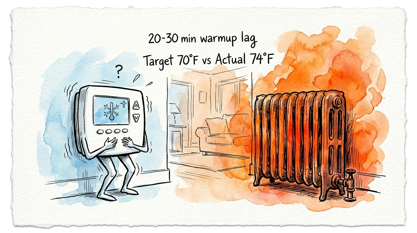
Cast-iron radiators do not respond quickly. It can take 20 to 30 minutes just to warm the iron castings before the surrounding air temperature registers any measurable change.
Because the air temperature remains flat, the thermostat assumes the home is under-heated. It keeps the boiler firing continuously at maximum aquastat temperature.
According to energy benchmarks from Energy Star smart thermostats, automated temperature setbacks save fuel only when the recovery cycle matches heating equipment characteristics.
When a stock thermostat finally hits its 70°F target and opens the relay, the radiator is fully saturated at 180°F. The radiator continues bleeding that stored heat, unintentionally roasting the room to 74°F.
Understanding steam heat smart automation highlights why hot water hydronics behave differently. Steam releases massive latent heat quickly at boiling point, whereas hydronic loops release sensible heat slowly across a declining temperature gradient.

Calculating Thermal Drift: A Step-by-Step Worked Example
To stop overshoot, you must determine your loop’s exact drift offset. This calculation identifies how many degrees early your smart thermostat or boiler relay must cut power.
Combining your drift offsets with comprehensive smart home energy monitoring tools allows you to objectively measure fuel savings after trimming runtime.
Follow this step-by-step procedure to measure your heating zone’s thermal inertia:
- Wait for a cold evening with stable outdoor temperatures between 25°F and 35°F.
- Allow the room to stabilize at a resting baseline temperature of 65°F.
- Raise the thermostat setpoint to 70°F to trigger a continuous boiler burn.
- Record the exact room temperature the moment your boiler relay cuts off.
- Log the room temperature every five minutes without opening doors until the reading peaks and begins falling.
Subtract the cutoff temperature from the peak temperature to determine your thermal drift offset.
Worked Scenario: The 350-Square-Foot Living Room
Consider a typical 1920s craftsman living room measuring 350 square feet with 9-foot ceilings. The room features two 4-tube, 26-inch, 10-section freestanding cast-iron radiators.
You can track whether your calculated offsets are cutting excess burner runtimes by learning how to read and understand your thermostat’s energy reports.
Together, these two radiators weigh approximately 240 pounds and hold roughly six gallons of water. Six gallons of water add another 50 pounds of mass, creating a 290-pound thermal battery.
In our test scenario, the boiler supply water runs at 180°F, and the room baseline is 65.0°F. The homeowner targets a steady 68.0°F comfort level.
- Burner engagement begins at 65.0°F indoor temperature.
- The boiler relay turns off when the thermostat detects 68.0°F at 7:45 PM.
- At 8:15 PM, the room temperature peaks at 71.2°F before slowly declining.
- Thermal drift calculation: 71.2°F peak minus 68.0°F cutoff equals 3.2°F total overshoot.
- Time to peak: 30 minutes of residual heat transfer after relay disconnection.
To maintain a stable 68.0°F in this scenario, the relay must disengage at 64.8°F during cold snaps. That 3.2°F anticipatory offset prevents the room from exceeding the desired comfort threshold.
Comparing Smart Relays and Thermostats for High-Mass Heating
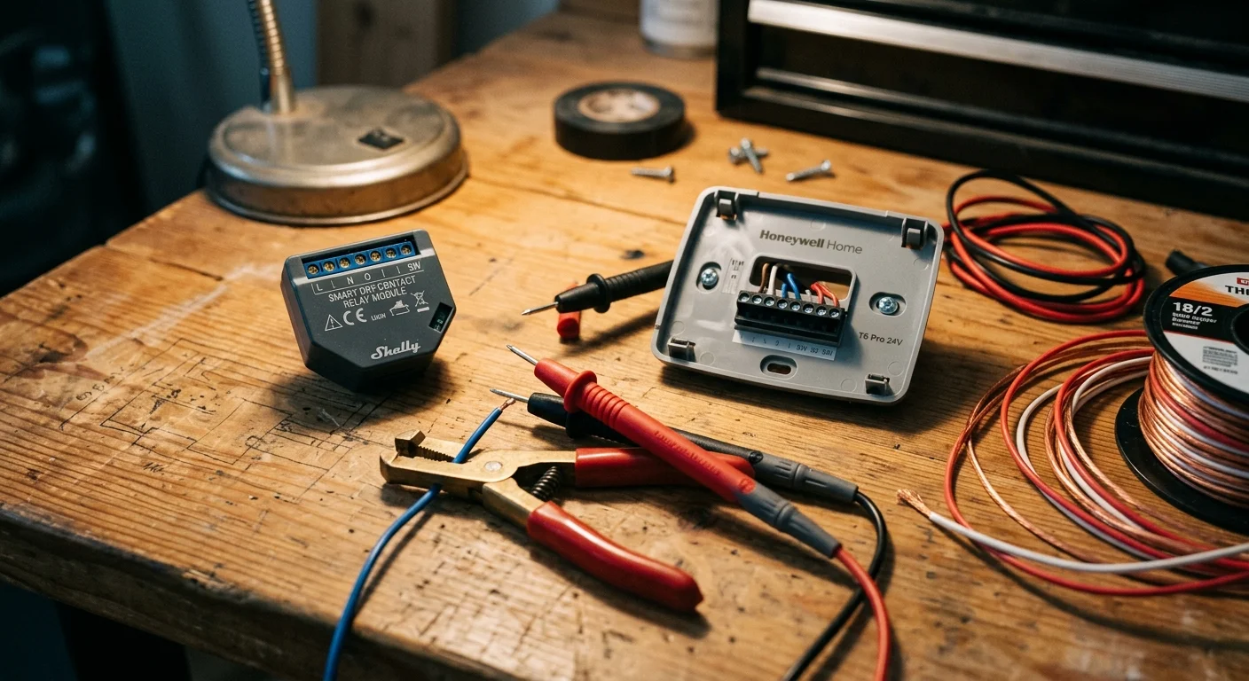
Not all smart thermostats give you access to the advanced parameters required for hydronic heating thermal drift smart control. Many budget models hide cycle rates and deadband configurations behind locked proprietary software.
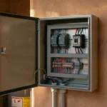
When housing dry-contact micro-relays inside tight electrical enclosures near your boiler, follow best practices for installing smart relays in shallow metal boxes to avoid thermal buildup.
According to device evaluations by Wirecutter smart home testers, sensor responsiveness and granular scheduling play pivotal roles in managing uneven heating systems.
The following table compares key hardware options based on their cycle control, setback anticipation capabilities, and relay integration types.
| Device Model | Heating Hardware Type | Cycle Rate / Differential Adjustability | Setback Anticipation Method | Power Wiring Interface |
|---|---|---|---|---|
| Ecobee Smart Thermostat Premium | Smart Low-Voltage Thermostat | Manual differential temp (0.5°F to 3.0°F) and minimum runtime control | Smart Recovery algorithm (self-adjusting based on ramp rates) | 24VAC with dedicated C-wire or Power Extender Kit (PEK) |
| Honeywell Home T9 | Smart Low-Voltage Thermostat | Dedicated Cycles Per Hour (CPH) setting (adjustable from 1 to 3 for hot water) | Adaptive Intelligent Recovery based on historical heating rate | 24VAC with mandatory C-wire connection |
| Shelly Plus 1 Relay | Wi-Fi Dry-Contact Smart Relay | Fully custom via Home Assistant automation loops and PID controller scripts | User-scripted mathematical offset factoring outdoor reset temperature | 110-240VAC line power or 12V/24V-48VDC; isolated dry contact outputs |
| Nest Learning Thermostat (4th Gen) | Smart Low-Voltage Thermostat | Fixed automatic software control (True Radiant learning mode) | Pre-heat calculation up to 5 hours early; limited manual override | 24VAC terminal with optional battery power stealing (C-wire recommended) |
If you prefer an out-of-the-box thermostat, select a model offering manual differential adjustments or dedicated hydronic cycle settings. Power users running Home Assistant achieve tighter control by wiring an isolated smart relay directly to the boiler aquastat.
Wiring Dry Contacts and Isolating 24V Boiler Terminals
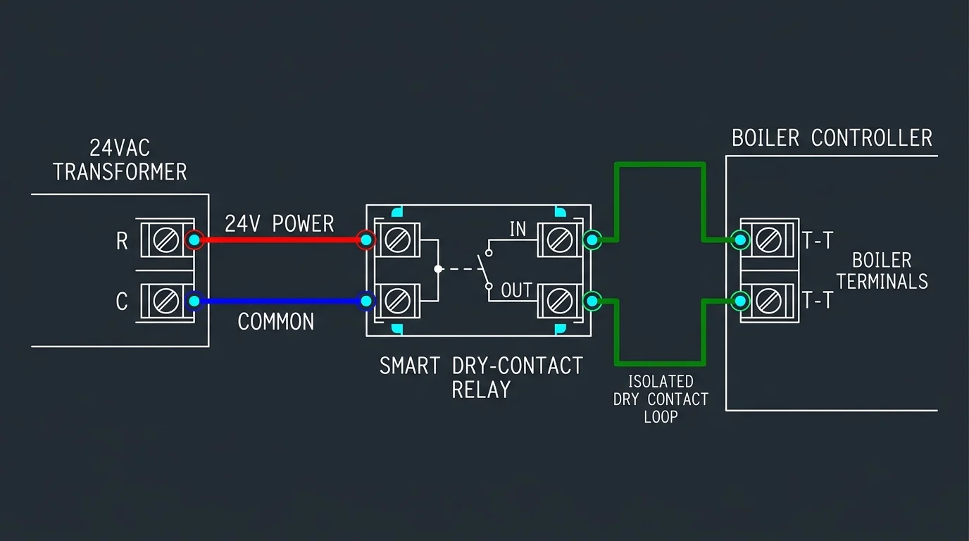
Vintage two-pipe radiator systems frequently feature antique two-wire thermostat circuits wired directly to a boiler relay box. These vintage circuits run between terminals labeled T and T on a switching relay like a Taco SR501.
If you automate heating via wireless smart relays, ensure you set up offline smart thermostat fail-safes so localized network drops never leave your radiators unpowered in freezing weather.
If you are upgrading your controls from scratch, our guide on how to install a smart thermostat yourself details fundamental terminal labels and low-voltage precautions.
A standard two-wire connection provides simple switch closure but lacks the continuous electrical path needed to power smart thermostats. Attempting to power a modern thermostat without a common wire leads to power-stealing issues.
Power-stealing thermostats draw tiny electrical currents through the heat circuit while the relay is off. On hydronic relays, this parasitic draw can cause relay chatter, false heating calls, or burnt transformer coils.
You have three reliable options for supplying clean 24VAC power to your smart thermostat on a two-pipe hydronic loop:
- Run a new multi-conductor thermostat cable with at least three conductors (R, W, and C) back to the boiler transformer.
- Install an external 24VAC plug-in transformer with an isolation relay to keep auxiliary power separated from boiler controls.
- Install an isolated dry-contact smart relay inside the boiler room, controlled wirelessly by remote room temperature sensors.
Never connect an external 24VAC transformer directly across boiler T-T terminals without a mechanical isolation relay. Introducing unsynchronized alternating current into your boiler controller can instantly destroy the main circuit board.
Always shut down line-voltage electrical breakers before opening any boiler control enclosure or stripping thermostat wiring. If your boiler controls use line-voltage 120V switching instead of low-voltage 24V wiring, hire a licensed electrician.
Configuring Anticipatory Setbacks and Cycle Rates
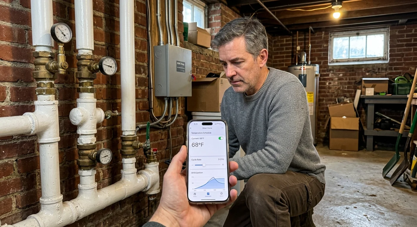
Once your hardware is installed, configuring software parameters correctly prevents thermal drift from wasting fuel. Factory defaults always favor fast-reacting forced-air furnaces, so you must override these baseline settings immediately.
Calibrating these anticipatory cutoffs is essential when learning how to create the perfect temperature schedule for high-mass hydronic zones.
Optimize Cycles Per Hour (CPH) and Deadbands
Forced-air furnaces often cycle three to six times per hour to maintain constant airflow. If you subject cast-iron hydronic heating to three cycles per hour, your boiler short-cycles while your radiators never fully heat.
Set your thermostat’s heating cycle rate to 1 or 1.5 cycles per hour. On thermostats using differential temperatures instead of CPH, set the minimum heating differential to 1.5°F or 2.0°F.
This wider threshold allows the radiator to heat up thoroughly, release its thermal mass, and cool down before re-engaging. You will experience longer, steady burns followed by hours of passive radiant heat dissipation.
Program Gradual Morning Recoveries
Avoid drastic temperature setbacks of more than four degrees Fahrenheit on high-mass hydronic systems. Dropping your thermostat from 68°F to 60°F overnight creates a massive thermal deficit in the building structure.
As outside temperatures drop sharply into midwinter, preparing your smart thermostat for seasonal changes ensures recovery timing stays accurate without causing early morning chill.
Because cold cast iron requires hours to recover, the system burns continuously for an extended window to overcome that deficit. When the target temperature is reached, the resulting thermal drift causes extreme daytime overshoot.
Implement an anticipatory setback schedule to smooth out your home’s heating curve:
- Limit overnight setbacks to no more than 3°F below your daytime comfort target.
- Schedule your morning wake-up recovery cycle to begin 90 to 120 minutes before your alarm sounds.
- Program your thermostat target 1.5°F lower than your desired wake temperature to account for thermal drift.
- Create an afternoon maintenance period with static setpoints to prevent mid-day boiler cycling.
- Initiate your evening setback 60 minutes before bedtime, letting residual radiator mass keep bedrooms comfortable.
Pairing this anticipatory schedule with smart thermostat cast iron radiators optimization creates perfectly level room temperatures. Your boiler burns less fuel, and your home avoids the suffocating heat spikes typical of old hydronic loops.
Frequently Asked Questions
How do I stop my cast-iron radiators from overshooting the thermostat setpoint?
To stop overshoot, calculate your system’s thermal drift and lower your thermostat cut-off target by that exact offset. You should also decrease cycle rates to 1 cycle per hour and widen heating differentials to at least 1.5°F.
Can I use a Nest thermostat with two-pipe hydronic cast-iron heating?
Yes, but you must enable Nest’s True Radiant setting and select radiators as your heat source. Providing a dedicated C-wire connection is strongly recommended to prevent boiler switching relay chatter.
Why does my boiler turn on and off so frequently with a smart thermostat?
Your smart thermostat is likely using factory cycle-per-hour settings tuned for forced-air systems. Change your heating equipment profile from furnace to high-mass hydronic radiators to force longer, less frequent heating cycles.
What is the best cycle rate setting for hot-water cast-iron radiators?
Set your thermostat to 1 cycle per hour (CPH) for cast-iron hot-water radiator heating systems. This cycle rate prevents boiler short-cycling and allows the heavy metal mass to distribute radiant warmth steadily.
Disclaimer: This article is for informational purposes only. Smart home devices involve electrical connections and data privacy.
Always follow manufacturer instructions for installation. For complex wiring or HVAC work, consult a licensed professional.