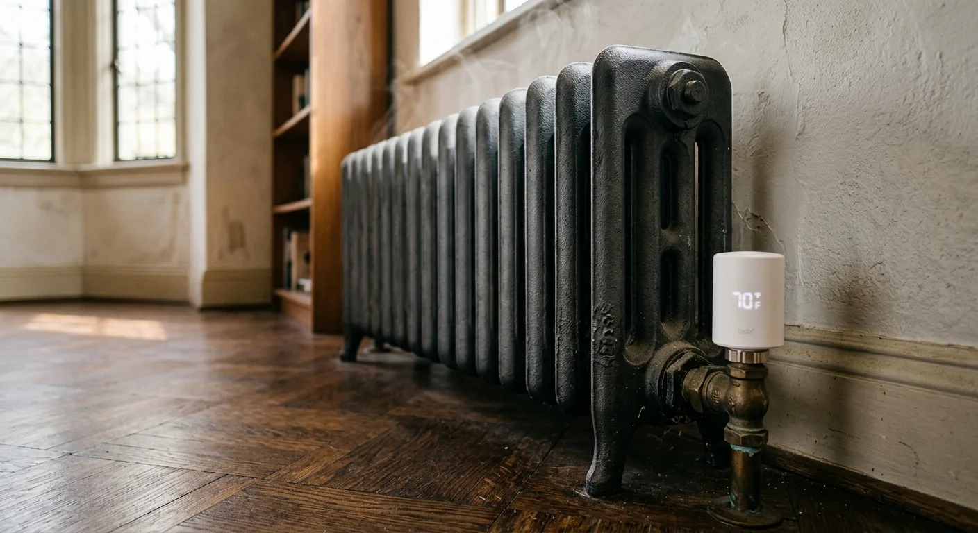
Your cast-iron radiators keep roasting your living space long after your smart thermostat hits its target temperature. Standard smart radiator valves shut off the moment a room reaches 70°F, yet the massive metal castings continue dumping stored heat for nearly an hour.
This thermal lag drives painful 2°F to 5°F room temperature overshoots that waste fuel and ruin your comfort. Taming a historic hydronic system requires programming a 30-minute anticipatory cutoff to absorb the iron flywheel effect.
Here is how to configure thermal dampening on your smart radiator valves to stabilize your home’s indoor climate.

The Physics of Cast-Iron Thermal Mass and Overshoot
Cast-iron radiators function as thermal batteries. Unlike modern steel panel radiators that cool rapidly, heavy iron sections hold immense volumetric energy.
A typical cast-iron radiator contains between 4 and 8 gallons of water inside hundreds of pounds of gray iron. That volume creates massive latent heat capacity.
When your boiler circulates 160°F water, the iron reaches that operating temperature slowly. Once heated, the iron continues radiating heat long after circulation ceases.
Standard thermostatic radiator valves operate on simple proportional or bang-bang logic. They close the valve pin only after detecting the room setpoint.
By the time your Energy Star certified smart thermostat or valve registers 70°F, the radiator is still fully saturated with boiling or near-boiling water.
That trapped water and metal continue emitting heat for 45 to 60 minutes into the room. This latent thermal discharge forces indoor temperatures up to 73°F or 75°F.
Engineers refer to this phenomenon as thermal flywheel overshoot. Eliminating it requires actively compensating for release delays before the room hits target thresholds.
Thermal inertia cannot be stopped at the valve; it must be anticipated before the setpoint is reached.

Steam Versus Hydronic Hot-Water System Boundaries
Before buying smart radiator valves, you must identify whether your heating system runs on low-pressure steam or closed-loop hydronic hot water.
Smart thermostatic radiator valves (TRVs) are built specifically for hydronic hot-water systems. They cannot regulate one-pipe steam systems without specialized modifications.
Hydronic hot-water loops circulate water between 120°F and 180°F under 12 to 20 PSI of closed pressure. The radiator has both an intake valve and a return pipe.
Low-pressure steam systems circulate gaseous vapor at 215°F or higher. These radiators feature a single supply pipe or an air vent on the opposite side.
If you screw a plastic-geared hydronic TRV onto a steam radiator, the 215°F steam can melt internal gears and destroy the silicone seals.
Steam radiator temperature overshoot requires smart air vents rather than smart supply valves. One-pipe steam systems must control venting rates rather than incoming vapor.
For hot-water radiators, smart radiator valve hydronic retrofits provide surgical flow control. Modulating the pin position restricts convective water currents with extreme precision.
Check your system pipes carefully before ordering hardware. If you see an air vent hissing vapor during a call for heat, you have steam.
Hardware Standards: M30 × 1.5 mm and Thread Retrofits
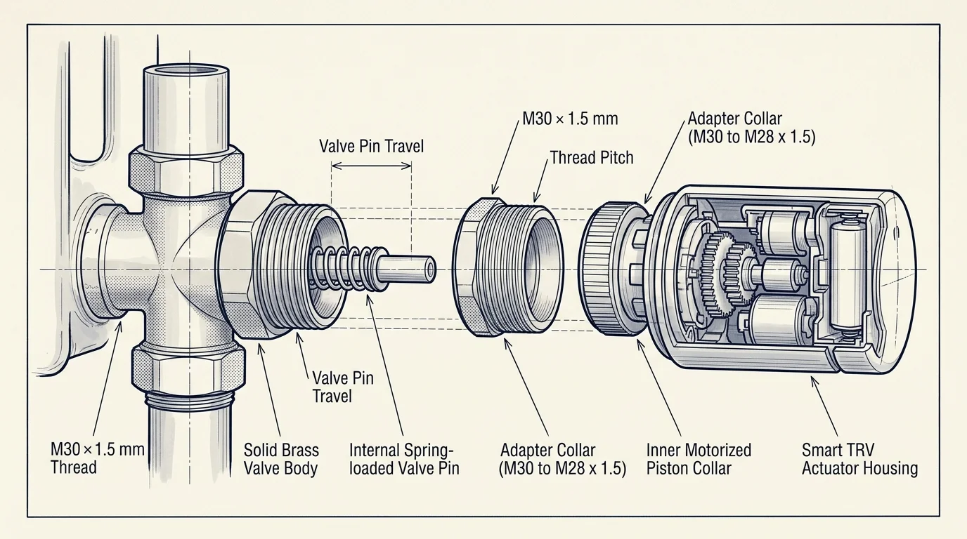
Most modern smart TRVs connect using an M30 × 1.5 mm metric threaded collar. This standard dominates European and contemporary hydronic plumbing fittings.
Historic cast-iron radiators in North America and older European buildings rarely feature M30 × 1.5 mm threads. Instead, they use manual packless angle valves.
You cannot mount a smart TRV head onto a vintage manual valve body. The manual valve uses a threaded rising stem rather than a spring-loaded push pin.
To use a smart valve, you must replace the existing radiator valve with a thermostatic valve body. This body houses the internal spring pin that actuators depress.
Identify your pipe sizing before draining the heating loop. Historic residential hot-water radiators typically utilize 1/2-inch, 3/4-inch, or 1-inch National Pipe Taper (NPT) pipe connections.
When installing new thermostatic valve bodies, choose brass bodies engineered for high-flow gravity or low-pressure pumped systems. Follow these physical preparation steps:
- Isolate the heating zone and drain the hydronic system down below the target radiator level.
- Unthread the vintage manual union spud from the radiator tapping using an internal spud wrench.
- Apply PTFE pipe paste and heavy-duty thread tape to the male threads of the new thermostatic spud.
- Thread the new M30 × 1.5 mm thermostatic valve body into the supply pipe and reattach the union nut.
- Refill the hydronic loop, bleed all trapped air from the radiator vent plug, and inspect for leaks at 20 PSI.
If your system already features thermostatic valves from brands like Danfoss, Giacomini, or Drayton, use matched metal adapters. Avoid flimsy plastic clip-on adapters that flex under actuator pressure.
Smart TRV Hardware Comparison for High-Inertia Heating
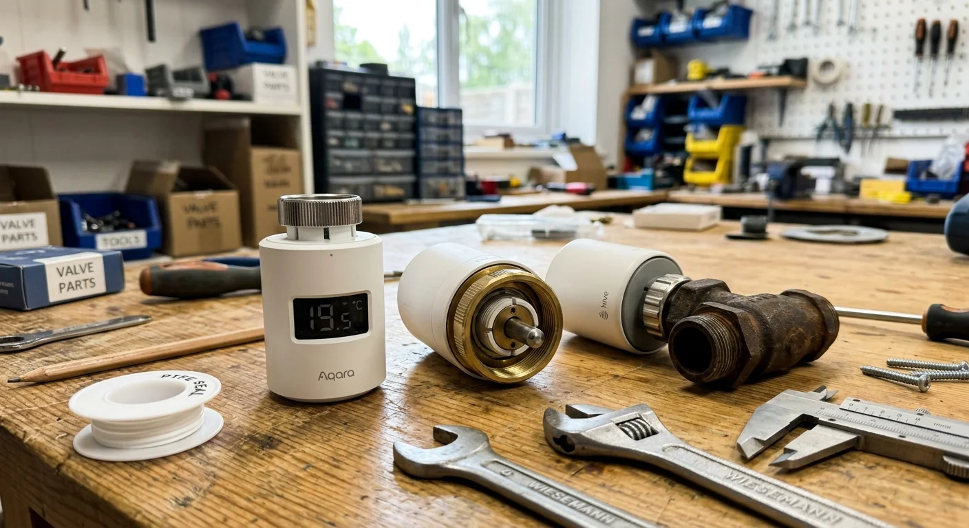
Controlling heavy cast-iron radiators requires smart valves with robust wireless communication and advanced temperature compensation. Basic standalone models lack the programmatic control needed to prevent lag.
Newer hardware designs support the Matter smart home standard, enabling seamless local integration across diverse smart home hubs. Local control eliminates cloud communication delays that compromise timing.
The table below compares three leading smart radiator valves evaluated for high-inertia hydronic systems.
| Device Model | Wireless Protocol | Unit Price Range | Decoupled Sensor Pairing | Algorithmic Overshoot Protection |
|---|---|---|---|---|
| Tado Smart Radiator Thermostat X | Thread (Matter) | $80 – $105 (€64 – €99) | Native wireless sensor sync | Dynamic self-learning thermal response |
| Eve Thermo | Thread (Matter) | $85 – $95 (€79 – €85) | Apple Home / Matter sensor link | Fixed temperature offset schedules |
| TP-Link Kasa KE100 | Sub-GHz (Dedicated Hub) | $50 – $65 | External sensor automation | Early valve shutoff calibration |
The Tado Smart Radiator Thermostat X excels on cast-iron systems because it natively tracks thermal run-up curves. It automatically learns how fast your room gains and loses heat.
The Eve Thermo offers completely local Matter-over-Thread operation without third-party cloud requirements. You can pair it directly to Apple Home or Home Assistant for local scripting.
The TP-Link Kasa KE100 provides a budget-friendly alternative with rapid motor actuation. However, preventing overshoot on the KE100 requires setting up external automation rules inside platforms like Home Assistant.

Configuring Anticipatory Cutoff Offsets and PID Dampening
Preventing temperature overshoot requires changing how your smart valves calculate closure points. Standard proportional algorithms fail because they assume heat transfer stops immediately when water stops moving.
On a cast-iron radiator smart thermostat setup, you must implement an anticipatory cutoff. This command shuts the valve pin 20 to 35 minutes before your room hits target temperature.
Alternatively, program a virtual target offset. If you desire a stable 70°F room temperature, configure the TRV target setpoint to 68.5°F during recovery phases.
The latent heat contained within the 200-pound iron casting will glide the room across the remaining 1.5°F gap. The room settles precisely at 70°F without crossing into 74°F territory.
Advanced home automations utilize Proportional-Integral-Derivative (PID) controllers. Integrations like Home Assistant’s Versatile Thermostat let you tune your heating cycle directly.
Apply these specific software settings inside your automation platform to stabilize high-mass hydronic zones:
- Set the derivative time (Td) higher to aggressively slow heat delivery as the room temperature approaches setpoint.
- Establish a minimum cycle duration between 3 and 7 minutes to protect the TRV motor from excessive wear.
- Relocate your temperature measurement source away from the radiator chassis using an external Zigbee or Thread sensor.
- Configure an early-cutoff threshold of 0.8°C (1.5°F) below the desired peak schedule.
- Enable slow-fill valve positioning if your TRV supports fractional percentage opening rather than binary open/close movement.
Never rely on the temperature sensor embedded inside the smart TRV head. That internal thermistor sits mere inches from the cast-iron body.
An integrated sensor registers 75°F while your living room couch remains at 65°F. Decoupling the sensor reading is mandatory for cast-iron climate control.

Worked Example: Calibrating a 1920s Living Room Radiator
Consider this real-world calibration scenario in a 1924 Craftsman bungalow living room measuring 280 square feet. The room features 9-foot ceilings, original lath-and-plaster walls, and single-pane wood windows.
Heating comes through a 6-column, 20-section cast-iron radiator. The bare assembly weighs approximately 240 pounds and holds 5.4 gallons of water.
The system water enters the radiator at 165°F. During initial testing with a standard smart TRV set to 69°F, the room suffered severe cycling swings.
The valve remained wide open until the integrated sensor reached 69°F at 7:15 AM. Circulation ceased, but the massive iron core continued radiating heat.
By 8:05 AM, the living room reached 73.6°F, creating a 4.6°F overshoot that remained uncomfortably hot until mid-morning. Fuel consumption spiked needlessly.
To eliminate this swing, we replaced the stock logic with a calibrated anticipatory workflow using the following hardware and settings:
- Installed an M30 × 1.5 mm smart TRV connected locally over Thread.
- Mounted a wireless temperature and humidity sensor at seated eye level, 12 feet away from the radiator.
- Set the smart schedule setpoint to 67.4°F instead of the desired 69.0°F comfort target.
- Configured an automation to cut the TRV valve position to 0% as soon as the room hits 67.5°F.
- Enforced a 35-minute coast period before evaluating any subsequent calls for additional heat.
With this 35-minute anticipatory coast active, the radiator stopped receiving hot water at 67.5°F. The latent heat carried the room temperature steadily upward.
Over the next 42 minutes, the room temperature climbed slowly, peaking at exactly 69.1°F before leveling off. The room remained within 0.5°F of target all morning.
This single adjustment eliminated the 4.6°F overshoot entirely. It reduced boiler run time for that zone by 18 minutes per heating cycle.

Integrating Central Smart Thermostats with Boiler Relays
Smart radiator valves only work effectively if water circulates through the system when heat is needed. In many homes, a single wall thermostat controls the central boiler burner.
If your central wall thermostat satisfies its setpoint, it turns off the boiler burner and primary circulator pump. When that happens, your individual smart TRVs cannot heat their rooms.
Independent analysis from Wirecutter’s smart home testing highlights the necessity of end-to-end HVAC system coordination. Individual room controls must communicate back to master switches.
To solve this master-slave conflict, connect your smart TRVs to your central boiler relay through software automation. When any smart TRV opens beyond 30%, trigger the boiler circulator pump.
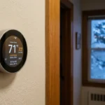
If you run a smart wall thermostat like an Ecobee or Nest, you need a common C-wire to power continuous radio communications. Constant power prevents disconnects during heating demands.
When wiring central boiler relays, implement the following architectural safeguards:
- Install an automatic pressure bypass valve near the boiler to handle situations where all smart TRVs close simultaneously.
- Maintain at least one uncontrolled bypass radiator in a hallway or bathroom to prevent deadheading the circulator pump.
- Use local wireless protocols like Zigbee or Thread rather than cloud integrations to ensure boiler shutoff commands execute reliably.
- Set a failsafe rule that cuts boiler firing if the automation controller loses contact with room sensors for more than 10 minutes.
Coordinate your central thermostat schedule with your TRV anticipatory setbacks. Never schedule conflicting calls for heat between the central controller and remote zones.
Troubleshooting Uneven Hydronic Heating and Valve Whistle
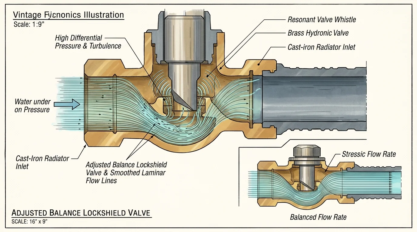
After installing smart TRVs on cast-iron radiators, homeowners occasionally encounter whistling sounds or uneven heating patterns across radiator sections. These issues stem from hydraulic imbalance.
Vintage gravity hydronic systems relied on large pipe diameters and low flow velocities. Modern circulator pumps force water through restricted valve pin openings, generating velocity noise.
When a smart TRV throttles down to 10% or 15% open, water rushes through the tiny aperture. The resulting pressure drop causes audible whistling or pipe vibration.
To eliminate valve whistling, install an adjustable differential pressure bypass valve (DPBV) across the boiler supply and return headers. The bypass relieves excess system pressure.
Uneven radiator heating—where the supply side stays scalding while the return side remains cold—indicates trapped air or poor flow balance. Resolve these issues using this procedure:
- Open the coin vent on the upper casting of the cold radiator using a radiator key until water emerges in a steady stream.
- Check the lockshield valve on the return pipe at the bottom of the radiator; ensure it is turned open 1.5 to 2.5 turns from closed.
- Increase the smart TRV minimum opening threshold from 0% directly to 20% to prevent the valve pin from hovering in high-whistle micro-gaps.
- Balance the entire system by slightly closing the return lockshield valves on radiators closest to the boiler room.
Balancing forces hot water evenly into distant radiators. This mechanical step ensures your smart valve automations respond smoothly without fighting water starvation.
Frequently Asked Questions
Can I install a standard hydronic smart TRV on a steam radiator?
No, standard hydronic TRVs cannot withstand the temperatures and operating pressures of steam heating. The 215°F steam degrades internal motor gears and melts synthetic seals, causing premature device failure.
How far ahead should I close a cast-iron radiator valve to stop overshoot?
You should close the valve 25 to 35 minutes before your schedule requires the target temperature. Heavy cast iron releases latent heat for up to an hour, easily gliding the room to its setpoint.
Where should I place the decoupled room temperature sensor?
Mount the sensor on an interior wall at seated eye level, approximately 8 to 15 feet away from the radiator. Keep it shielded from direct sunlight, drafts, and direct thermal radiation.
What thread adapter do I need for older cast-iron radiator valves?
Most modern smart TRVs feature an M30 × 1.5 mm threaded connection. Vintage radiators usually lack this interface, requiring you to replace the manual valve body or install a matched metal adapter.
Disclaimer: This article is for informational purposes only. Smart home devices involve electrical connections and data privacy. Always follow manufacturer instructions for installation. For complex wiring or HVAC work, consult a licensed professional.