Your two-story colonial does not need an expensive secondary HVAC zone to eliminate a sweltering 10°F summer upstairs heat gap. You can balance your home by pairing smart thermostat multi-sensor weighting with automated register booster fans calibrated to specific airflow deficits.
Most standard advice recommends closing downstairs vents, but that tactic chokes static pressure and risks freezing your air conditioning coil. This guide provides the airflow cubic-feet-per-minute calculations and smart automation blueprint to equalize temperatures across both floors without damaging single-stage equipment.
By targeting airflow delivery directly at upper bedrooms, you restore comfort while preserving equipment efficiency.
The Physics of the Second-Floor Heat Split
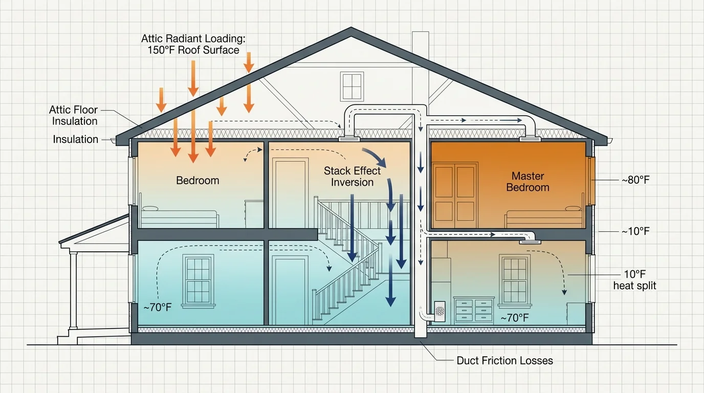
Uneven cooling single stage hvac setups suffer from two compounding thermal loads. Solar radiation superheats your roof and attic floor, while natural convective buoyancy pulls cool air down your staircase.
In homes prone to thermal stratification, implementing smart thermostat fan circulation cycles can help redistribute stagnant air between heating and cooling calls.
Duct runs feeding upper levels must overcome friction and gravity across extra vertical distance. As a result, supply registers upstairs deliver significantly lower air velocity than identical registers downstairs.
Space heating and cooling account for roughly 50% of residential energy consumption, according to the U.S. Department of Energy.
Overcooling your ground floor to force chilled air upstairs wastes electricity and creates an uncomfortably cold living room. Smart climate research from Consumer Reports on smart home systems highlights that targeted zone balancing delivers far better efficiency than thermostat cranking.
- Attic Radiant Loading: Roof shingles reach 150°F on hot days, radiating heat directly through attic insulation into upstairs ceilings.
- Stack Effect Inversion: Heavy, conditioned cold air sinks through open stairwells while rising warm air pools along upper-level ceilings.
- Duct Friction Losses: Extended duct runs and multiple elbows rob second-floor branch lines of static velocity before air reaches the room.
The Static Pressure Danger of Manual Vent Closing
Many homeowners try to redirect airflow by closing supply dampers on the ground floor. This common practice frequently causes severe mechanical failure inside your HVAC cabinet.
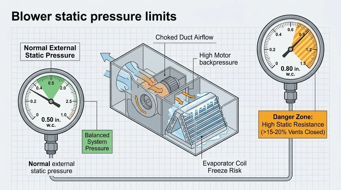
Residential single-stage systems require an external static pressure around 0.50 inches of water column (in. w.c.) across the blower motor.
Standard residential HVAC blowers require balanced external static pressure to protect the compressor and maintain heat transfer efficiency across the evaporator coil.
Closing more than 15% to 20% of your supply registers pushes system static pressure above 0.80 in. w.c.
When resistance climbs, airflow velocity across the indoor evaporator coil drops sharply. Chilled refrigerant cannot absorb sufficient heat, causing moisture on the coil fins to freeze into solid ice.
Solid ice blocks all remaining airflow, starving the compressor of cool return vapor and eventually causing complete mechanical burnout. You must pull air upstairs rather than restricting ground-level supply vents.
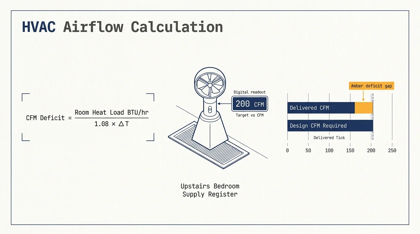
Calculating Your Upper-Floor CFM Cooling Deficit
Airflow balancing requires measuring cubic feet per minute (CFM) for each problem room. A standard residential cooling system delivers approximately 400 CFM per ton of nominal capacity.
A three-ton air conditioner circulates roughly 1,200 CFM through the central supply plenum. In two-story homes, the upper floor typically demands 60% of that total volume during mid-afternoon peak heat.
You can determine your upper floor’s exact cooling shortfall using a three-step airflow assessment:
- Calculate Target CFM: Multiply total system CFM by the room’s share of upper-level square footage, then add a 15% thermal solar buffer.
- Measure Supply Velocity: Hold a handheld digital anemometer over the register grille to record air speed in feet per minute (FPM).
- Calculate Actual CFM: Multiply measured FPM by the register grille’s free core area in square feet.
If a room requires 160 CFM but your anemometer registers only 65 CFM, your duct branch carries a 95 CFM cooling deficit.
Knowing this deficit enables you to select booster hardware that delivers the exact mechanical assist needed to bridge the gap.
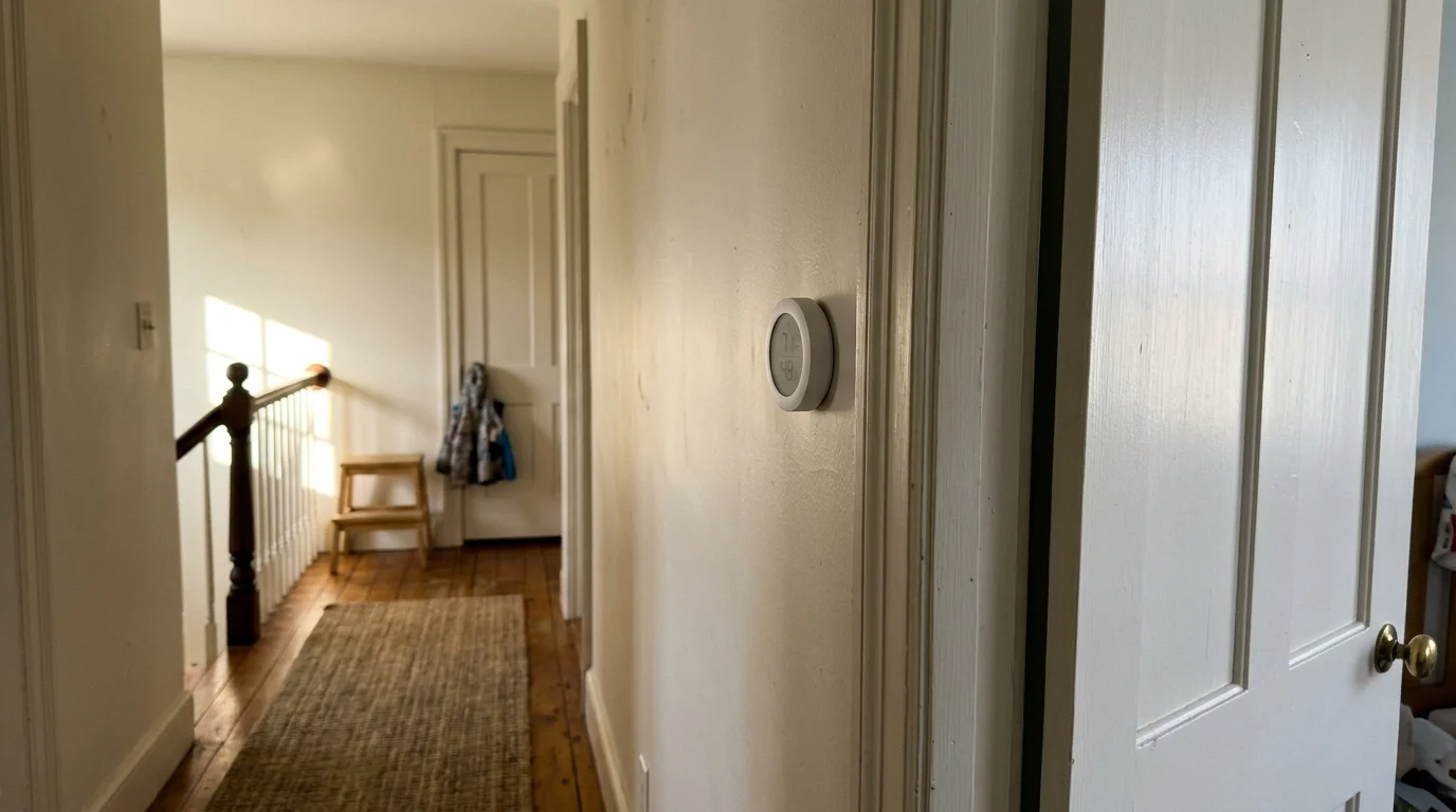
Multi-Sensor Smart Thermostat Weighting Strategies
A smart thermostat mounted in a ground-floor hallway only knows ground-floor conditions. To fix hot second floor smart thermostat blind spots, you must distribute remote sensors throughout upper bedrooms.
Modern Energy Star certified smart thermostats support multi-sensor averaging to redistribute system runtime dynamically based on regional demands.
The ecobee SmartThermostat pairs with SmartSensors ($99.99 for a 2-pack) communicating over a proprietary 915 MHz frequency up to 60 feet. These battery-powered sensors track both ambient temperature and occupancy.
ecobee uses a “Follow Me” algorithm to average temperatures only across rooms with detected motion. During nighttime sleep schedules, the system shifts its control priority entirely to second-floor bedroom sensors.
Google Nest offers the Nest Temperature Sensor (2nd Gen), released in August 2024 for $39.99 per unit. Nest units use Bluetooth Low Energy with a three-year battery life.
Rather than detecting occupancy, Nest relies on time-block sensor prioritization. You can instruct Nest to read exclusively from second-floor sensors during afternoon and evening cooling blocks.
Proper sensor positioning prevents false readings from distorting your thermostat’s runtime calculations:
- Mount at breathing height: Place sensors approximately 5 feet off the floor on an interior wall.
- Avoid direct sunlight: Ensure window glare never strikes the sensor face during afternoon solar peaks.
- Keep clear of supply vents: Position sensors at least 6 feet away from registers to prevent short-cycling from direct discharge drafts.
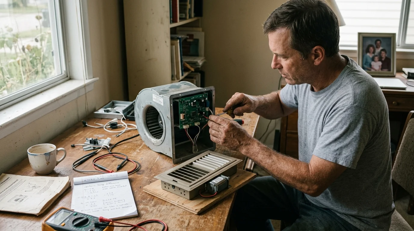
Automated Register and In-Duct Booster Fan Selection
Sensor weighting forces your single-stage equipment to run longer, but it cannot fix duct friction losses alone. A smart duct booster fan mechanically accelerates airflow through restricted second-floor branches.
Booster fans fall into two installation categories: register booster grilles and in-duct inline fans. Register booster grilles install directly into floor or wall openings without duct cutting.
The AC Infinity AIRTAP series ($49.00 to $59.99) fits standard 4″×10″, 4″×12″, and 6″×10″ supply boots.
Each AIRTAP unit houses a 12V DC motor drawing only 8 watts while producing 120 to 160 CFM of active airflow. Dual ball bearings keep sound levels whisper-quiet between 16 and 20 dBA.
An integrated thermal probe inserts directly into the duct boot below the grille. When the probe detects chilled air below your target trigger temperature, the fan activates automatically.
When the air conditioner shuts down and duct air warms, the booster switches off. This prevents the fan from circulating warm room air when cooling ends.
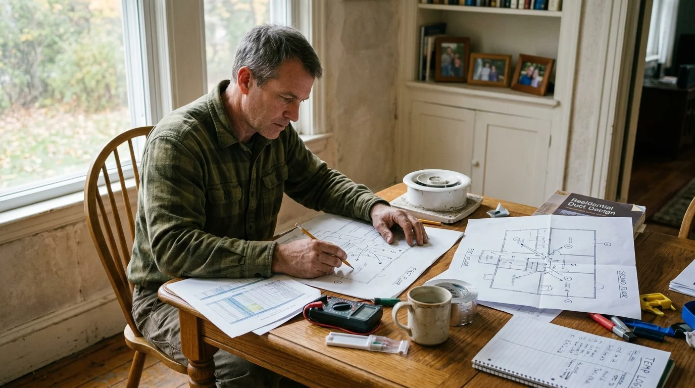
Worked Example: Balancing a 2,400-Square-Foot Colonial
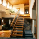
Here is a real-world scenario demonstrating airflow calculations and automation in a 2,400-square-foot colonial home.
The house uses a 3-ton single-stage air conditioner outputting 1,200 CFM. On an 88°F July afternoon, the downstairs thermostat reads 72°F while the primary upstairs bedroom reaches 82°F.
The primary bedroom measures 15 by 20 feet (300 square feet) with two west-facing windows and an unconditioned attic overhead. This room requires approximately 165 CFM of cooling air.
Testing the existing 4″×10″ supply register with an anemometer reveals an air velocity of 275 FPM. Through an effective free area of 0.22 square feet, the duct delivers only 60.5 CFM.
The room faces an active airflow deficit of roughly 104.5 CFM (165 target CFM minus 60.5 actual CFM).
To resolve the gap, the homeowner installs an AC Infinity AIRTAP T4 register booster fan ($49.00) and places an ecobee SmartSensor ($49.99) on the bedroom nightstand.
The booster fan’s thermal probe is set to trigger cooling mode at 64°F on fan speed setting 5, delivering 130 CFM.
At 9:00 PM, the ecobee shifts weighting exclusively to the bedroom sensor with a 73°F sleep setpoint. The booster fan activates 45 seconds after the central blower engages, pulling chilled air directly into the room.
Total equipment investment was $98.99. Within 48 hours, the second-floor evening temperature split fell from 10°F down to 1.5°F without freezing the evaporator coil.
Step-by-Step Booster Fan Integration and Automation
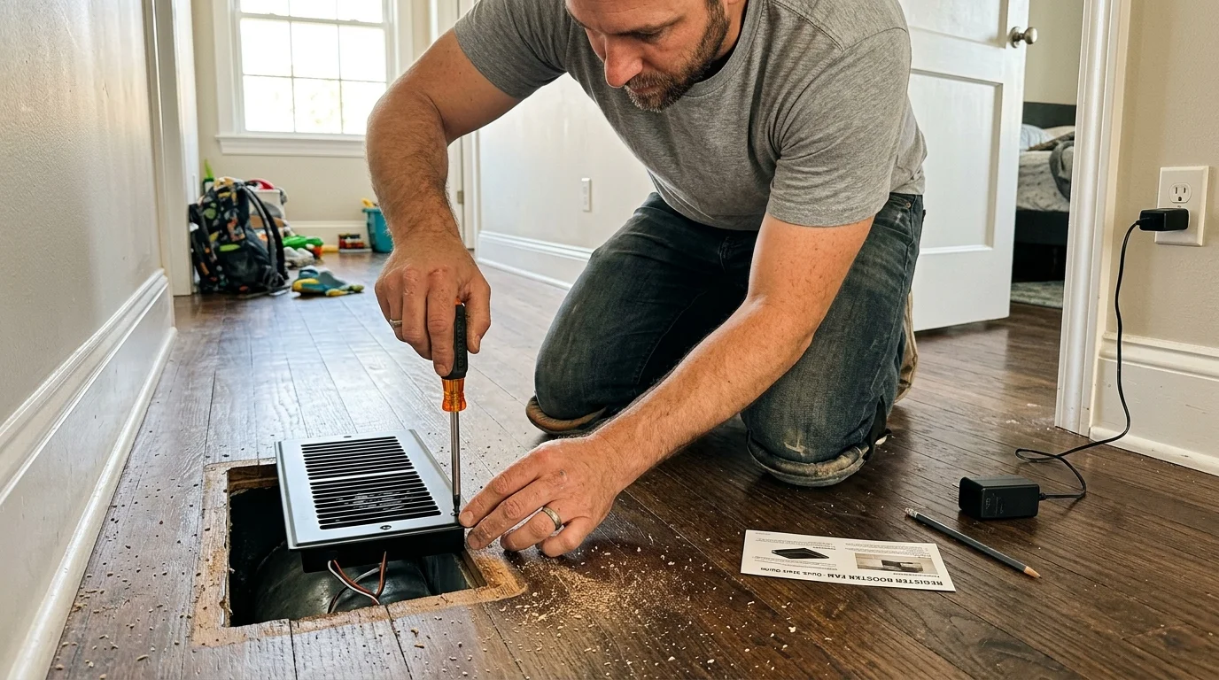
Installing and calibrating automated booster hardware requires straightforward tools and zero sheet metal cutting. Follow these step-by-step instructions to integrate your devices properly:
- Measure register dimensions: Lift your existing floor or wall grille and measure the duct opening’s width and length to ensure proper sizing.
- Position the power supply: Verify that a standard 120V wall outlet sits within 6 to 10 feet of the register to accommodate the 12V DC power brick.
- Insert the thermal probe: Extend the wired sensor probe 6 to 12 inches down into the supply duct boot where passing air velocity is highest.
- Seat the fan assembly: Drop the booster fan flush into the register opening and secure it to subflooring using the included mounting screws.
- Calibrate thermal setpoints: Turn on your cooling system, wait five minutes for steady duct temperatures, and configure the fan’s cooling trigger 4°F above the duct’s lowest reading.
- Configure thermostat schedules: Add your upper-level remote sensors to your smart thermostat’s evening and sleep profiles to align central blower runtimes with booster operation.
Test your system across two complete cooling cycles to confirm that the booster fan starts and stops within 60 seconds of central blower transitions.

Balancing Hardware Comparison
Different balancing methods offer distinct trade-offs between airflow velocity, acoustic disturbance, and duct pressure effects.
Review this comparison of residential balancing solutions before purchasing hardware for your home:
| Hardware Solution | Airflow Delivery | Acoustic Output | Power Draw | Static Pressure Impact | Hardware Cost |
|---|---|---|---|---|---|
| AC Infinity AIRTAP T4 (Register Booster) | 120–160 CFM (Active Pull) | 16–20 dBA | 8 W (12V DC) | Reduces branch pressure slightly | $49.00–$59.99 |
| Suncourt Inductor 6-Inch (Inline Duct Fan) | 160–250 CFM (Active Pull) | 45–52 dBA | 30 W (120V AC) | Significantly relieves branch resistance | $40.00–$65.00 |
| Flair Smart Vent (Automated Register Damper) | 0 CFM (Passive Restrictor) | Silent (Motor movement only) | 2x C-Batteries (or 24V) | Increases system static pressure | $99.00 per vent |
| ecobee SmartSensor (Sensor Weighting Alone) | 0 CFM (Thermostat Runtime Only) | Silent (No moving parts) | CR2477 coin cell (5-year) | Neutral (Maintains baseline duct curve) | $99.99 (2-pack) |
Register booster fans paired with smart sensors provide the best combination of low acoustic noise, minimal installation effort, and safe static pressure levels.
Frequently Asked Questions
Will smart duct booster fans damage my single-stage HVAC blower motor?
No, register booster fans do not harm your central blower. Unlike closed dampers that restrict airflow, booster fans actively draw air through ductwork, slightly reducing branch static pressure without straining the main blower.
Can I use automated smart vents instead of booster fans to balance temperatures?
Smart vents redirect air by closing lower-floor dampers, which increases total system static pressure. On single-stage systems, closing too many vents risks freezing your evaporator coil, making active booster fans a much safer option.
Where should I mount remote temperature sensors upstairs for optimal accuracy?
Mount sensors 5 feet off the floor on an interior wall away from direct sunlight, exterior doors, and register supply streams. This height accurately reflects human comfort and prevents localized drafts from triggering false cycles.
Why does my second floor feel humid even when temperatures equalize?
Single-stage air conditioners run at fixed speeds, sometimes cooling rooms quickly before removing sufficient moisture. Setting your thermostat fan to Auto rather than On ensures condensed coil moisture drains away rather than blowing back into bedrooms.
Disclaimer: This article is for informational purposes only, as smart home devices involve electrical connections and data privacy. Always follow manufacturer instructions, and consult a licensed HVAC technician for complex equipment work.