
Homeowners running a 24VAC smart thermostat on an older gas furnace often see the screen go black the second the burners ignite. That reset rarely signals faulty thermostat hardware or a Wi-Fi bug when preparing smart thermostats for seasonal changes.
The most common real-world cause of a thermostat restarting during a heat call is a clogged air filter tripping the furnace high-limit switch after 3 to 8 minutes, which cuts 24VAC power. When a restart happens the instant burners ignite instead, combining ignition relays, smart thermostat load, humidifiers, or zone dampers on a heat-weakened 40VA transformer—or using power-stealing without a C-wire—can pull secondary voltage below a smart thermostat’s 19.5VAC brownout threshold, even though a standard 24VAC dual-operator gas valve draws only roughly 12VA to 17VA (0.5A–0.7A). Confirming a true ignition voltage collapse with a multimeter before upgrading restores steady power.
Checking Compatibility and Buying a 75VA Transformer
First confirm your furnace uses a standard 24VAC integrated furnace control (IFC) board rather than line-voltage smart controllers for electric baseboard heaters. Verify you are not swapping a communicating inverter thermostat for 24VAC hardware.
Factory 40VA transformers supply 1.67 amps continuous output and up to 2.1 amps peak inrush under 100ms. Concurrent winter heating loads overwhelm that ceiling the millisecond the gas valve pulls open.
- Furnace Control Board: Draws 5VA to 8VA continuously for logic operations.
- Inducer and Blower Relays: Draw 4VA to 6VA of holding power.
- Smart Thermostat Load: Consumes 3.5VA to 7VA on a Google Nest Learning Thermostat, Honeywell Home T9, or Ecobee Smart Thermostat Premium.
- Gas Valve Solenoid: Draws roughly 12VA to 17VA (0.5A to 0.7A) with both operators energized; extra loads like humidifiers, zone dampers, or contactors can still push a heat-aged 40VA transformer past its limit.
Skip mid-capacity 50VA replacements, which offer 2.08 amps continuous and 2.8 amps peak inrush. That tight margin leaves smart thermostats, sensors, or smart thermostats for multiple zones exposed during ignition spikes.
If total accessory load exceeds 40VA, upgrade to a UL Listed Class 2 75VA multi-tap transformer with a built-in 3.2A circuit breaker, such as the Packard PF52475 (wiring the 120V primary leads and capping unused 208/240/480V taps). Do not slap a 75VA transformer onto an IFC board with a 3A automotive blade fuse without first verifying your board’s 3A or 5A low-voltage fuse rating and manufacturer limits.
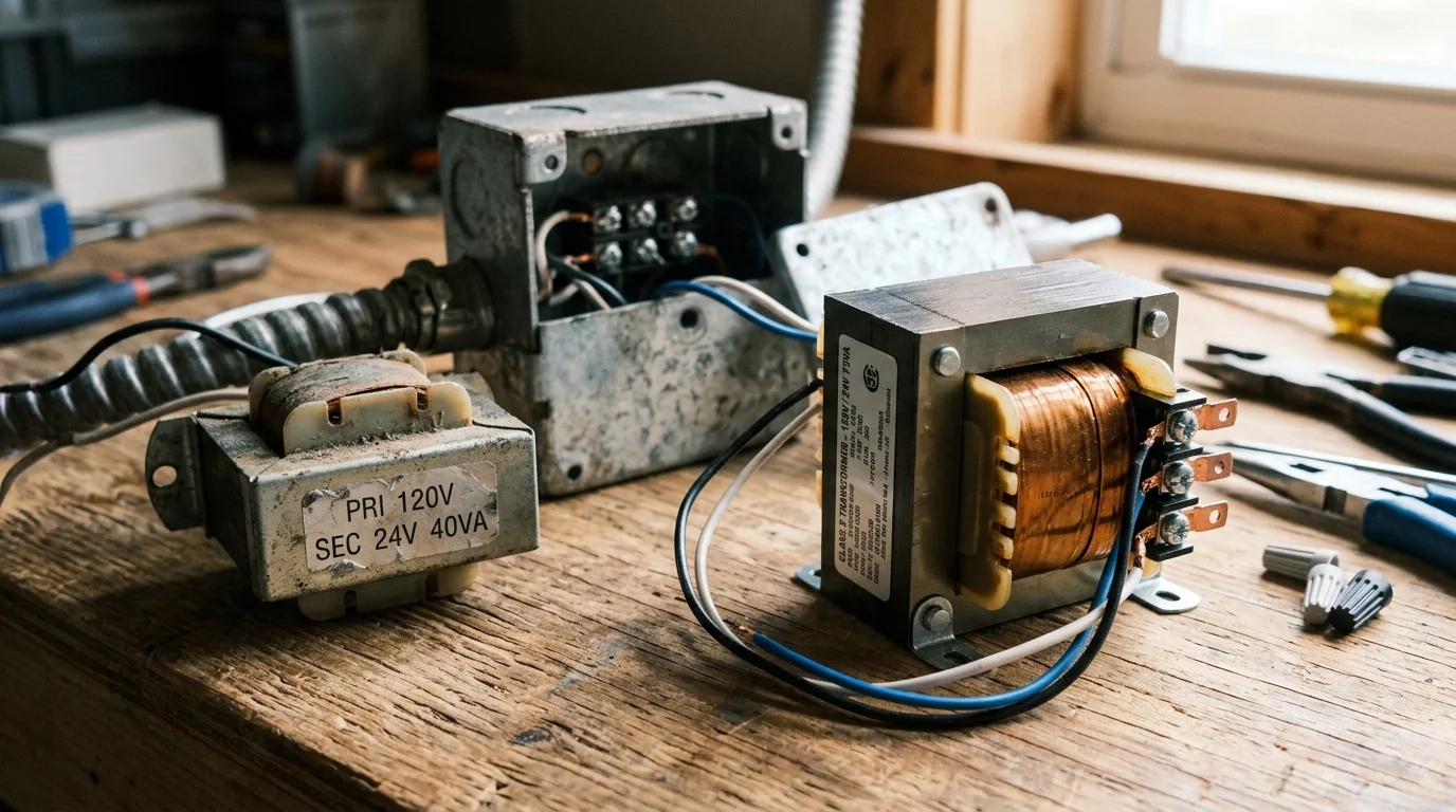
Gather a digital multimeter like a Fluke 116, wire strippers, twist-on wire nuts, and screwdrivers before opening the cabinet. Confirm transformer ratings and thermostat power specs on each manufacturer page before buying.
Inspect the new label for 120VAC input, 24VAC output, and 75VA capacity, and test the reset button for smooth movement. Do not unbolt the old unit until multimeter testing confirms an ignition voltage sag rather than a safety trip.
Isolating the Ignition Voltage Sag at the Wall Sub-Base
Most troubleshooting guides miss how heavily gas valve energization loads the 24VAC circuit. If you know how to install a smart thermostat yourself, testing the wall sub-base takes under twenty minutes.
Set your multimeter to AC Voltage (VAC) with the black probe in COM and the red probe in the Voltage port. Run these checks before touching furnace wiring:
- Check Standby Baseline: Remove the faceplate and test across R or Rh and C for a reading between 24.0VAC and 28.0VAC.
- Trigger a Heat Call: Reattach the faceplate, start a heat call, and hold probes on the exposed R and C screws.
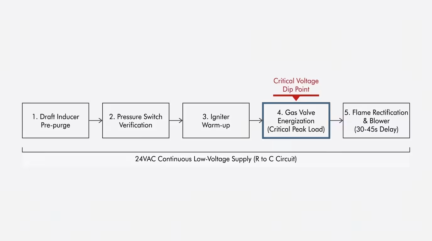
- Watch Pre-Purge and Igniter Warm-Up: Confirm voltage stays steady through the 15-second pre-purge and 17-second hot surface igniter warm-up, which pulls 120VAC line power.
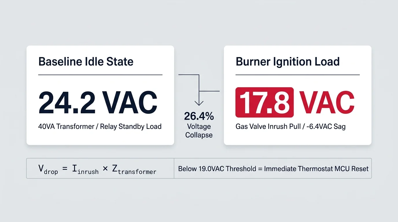
- Catch the Gas Valve Click: Look for an instant sag below 19.0VAC the millisecond the gas valve opens, forcing a thermostat reboot.
On an older 2008 Carrier 58STA furnace, an Ecobee Smart Thermostat Premium needed 19.5VAC to stay online. Voltage held at 24.2VAC through igniter warm-up before collapsing to 17.8VAC at burner ignition.
If voltage drops straight to 0.0VAC instead, stop the swap because a high-limit switch opened. Test across the two insulated limit switch terminals in the blower compartment, which jump from 0.0VAC to 24VAC when open.
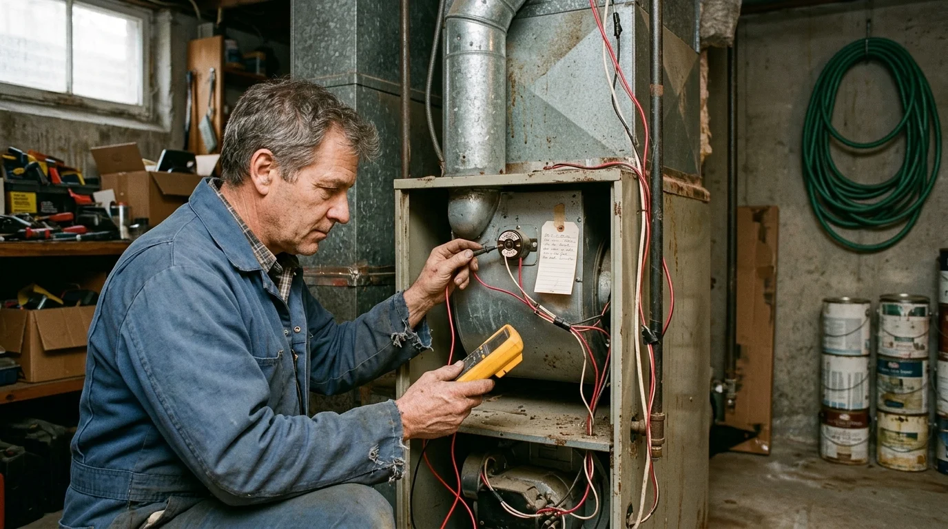
Carrier, Goodman, and Lennox boards wire safety switches in series with 24VAC output, severing R power when trapped heat opens the bimetallic disc. Resolve return air restrictions or adjust the heating fan speed tap before moving forward.
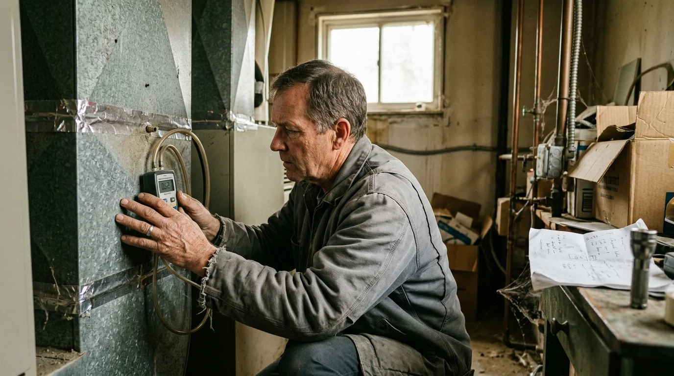
Move to the transformer swap only after confirming a momentary sag below 19.0VAC at ignition. If your meter reads 0.0VAC, fix airflow first so the safety loop stays closed.
Disconnecting Power and Removing the Factory 40VA Unit
Shut off the dedicated HVAC breaker at your main panel and flip the furnace service switch off. If working in an unattended home during winter freezes, enable offline smart thermostat fail-safes beforehand.
Pull off the upper and lower furnace doors to reach the blower housing and control board. Most cabinets include a door interlock switch that disconnects line power when opened.
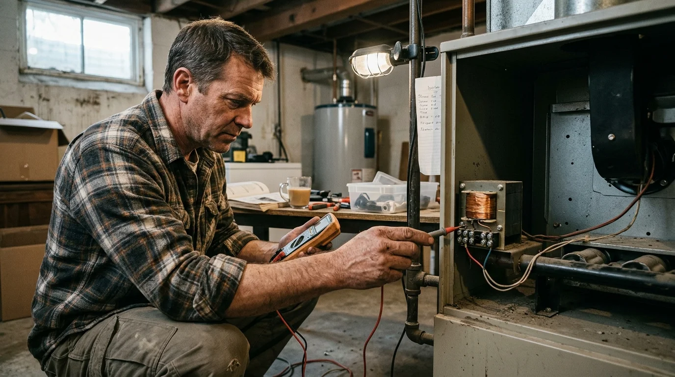
Verify power is dead across the 120VAC line terminals on the control board with a non-contact voltage tester and multimeter (0.0VAC and dark indicator lights) before touching wires. Photograph the existing connections, then unbolt and disconnect the factory 40VA transformer.
Before handling the replacement unit, verify every disconnected primary and secondary lead is clearly labeled or visible in your reference photo.
Mounting and Wiring the 75VA Replacement Transformer
Position the larger 75VA frame over the blower housing opening and dry-fit the cabinet door before driving screws. Keep the transformer clear of the blower wheel and wiring harnesses while leaving the reset button accessible.
Tighten the mounting screws firmly against blower vibration. Following the transformer and furnace wiring diagrams and local code, splice the 120VAC hot and neutral leads to the matching 120V primary leads with wire nuts (individually capping any unused 208/240/480V taps), then connect the 24VAC secondary leads to the control board; hire a licensed HVAC technician or electrician if unsure.
Verify your thermostat draws power over dedicated R and common (C) wire conductors rather than using smart thermostats that work without a C-wire. Power-stealing setups remain far more vulnerable to ignition voltage dips.
Before closing the furnace doors, tug every wire nut to confirm solid copper connections. Verify no bare copper touches sheet metal and keep low-voltage wires away from hot surfaces.
Restoring Power, Re-Pairing, and Testing Ignition Voltage
Refit both furnace doors securely so the interlock switch closes, then restore the service switch and main breaker. Leave the thermostat faceplate off briefly to verify wall standby voltage first.
Confirm a clean 24.0VAC to 28.0VAC baseline across R and C, which typically settles near 27.2VAC after a 75VA upgrade. Snap the faceplate onto the sub-base so it boots and reconnects to Wi-Fi and its app.
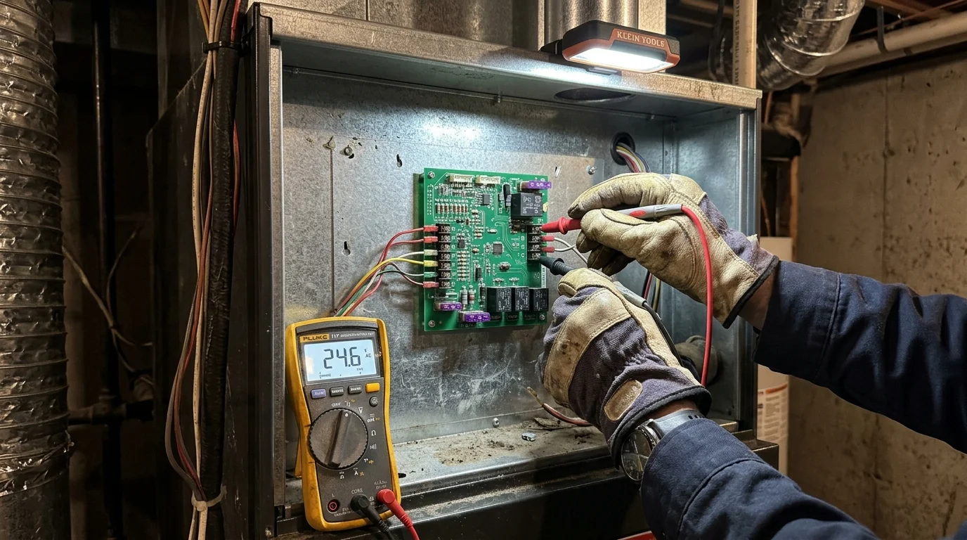
Trigger a heat call from the thermostat or app while holding your meter probes on R and C through ignition. Under the 75VA supply, voltage dips slightly to around 24.6VAC instead of collapsing below 19VAC.
Before leaving the furnace, verify the burners stay lit, the main blower starts 30 to 45 seconds later, and the screen never flickers. Do not move on to app checks if any restart still occurs.
Checking App Settings, Airflow Balance, and Runtime Logs
Open the Nest, Ecobee, or Honeywell Home T9 app after one full heat cycle to confirm continuous online status. Devices validated through Energy Star Smart Thermostats need clean 24VAC power to maintain programmed efficiency.
Testing by Wirecutter Smart Home likewise notes that smart climate controls require stable electrical power to deliver reliable performance. Review how to read your thermostat’s energy reports to confirm recurring short-cycling dropouts have cleared.
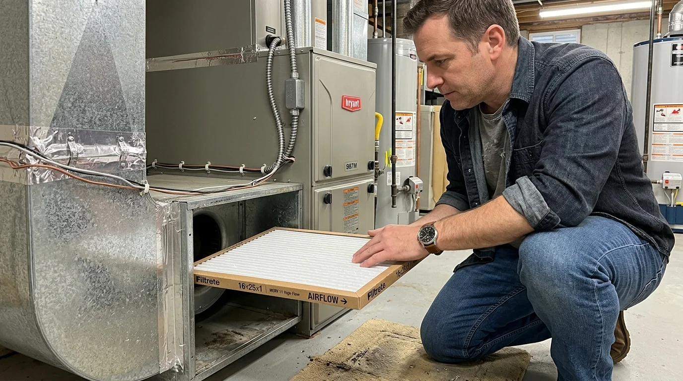
Verify at least 80 percent of supply registers stay open and return grilles remain clear of rugs or furniture. Use smart thermostat fan circulation cycles or fixing an upstairs heat gap to balance rooms instead of closing vents.
Watch one complete heating cycle reach setpoint in the app with no voltage resets before putting your tools away.
Disclaimer: This article is for informational purposes only. Smart home devices involve electrical connections and data privacy. Always follow manufacturer instructions for installation. For complex wiring or HVAC work, consult a licensed professional.


1 Comment