
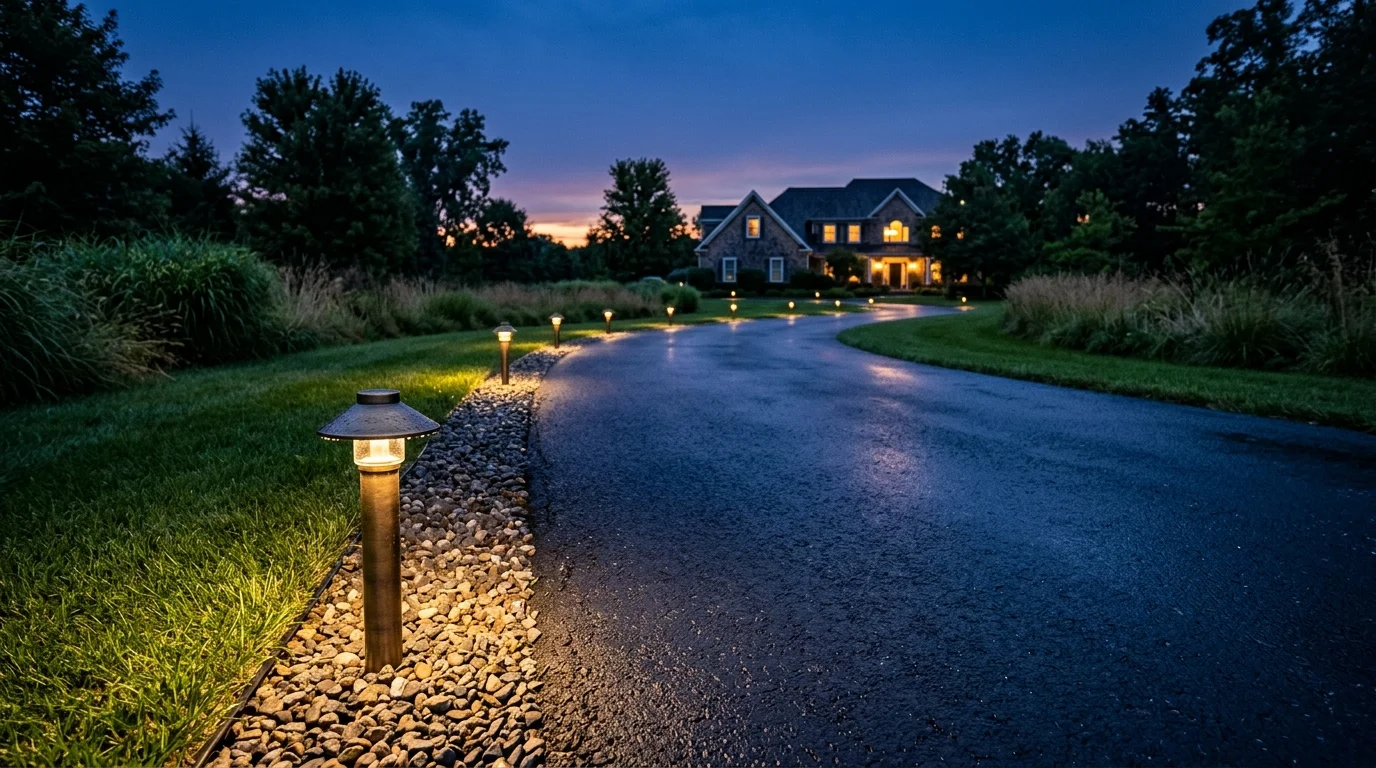
Sizing low-voltage smart landscape lighting along an un-sleeved, 120-foot asphalt driveway presents a hidden electrical hurdle. Standard calculators assume simple resistive bulbs and completely overlook the parasitic standby draw of smart wireless transceivers.
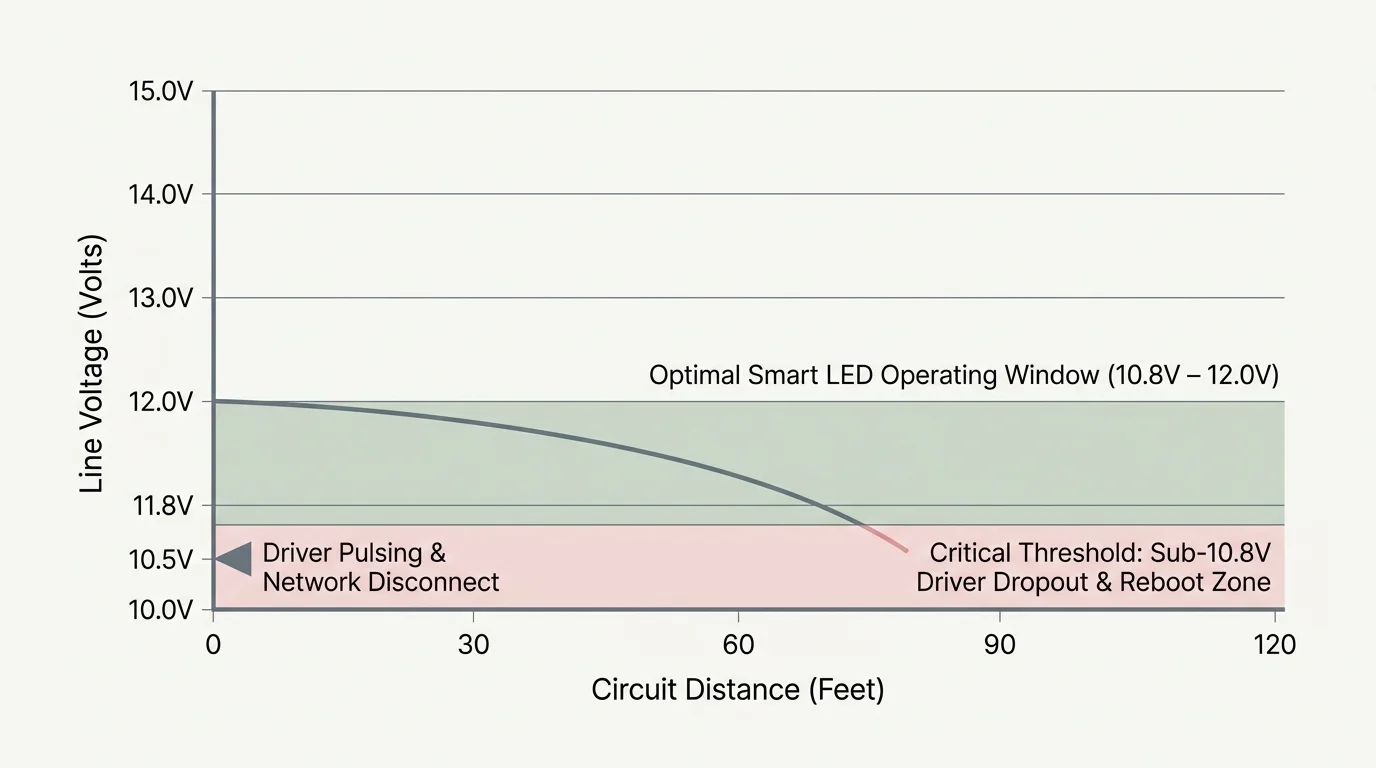
Modern Thread-over-Matter path lights require stable operating voltage to maintain mesh communication. When line voltage falls below 10.8 volts at the end of a long run, smart bulbs flicker, drop off your mesh network, and fail.
You do not need to trench through existing asphalt to fix this issue. Calculating your true transceiver-adjusted wattage and selecting a transformer with 14-volt or 15-volt multi-tap terminals ensures reliable automation across your entire perimeter.
The Physics of Voltage Drop on Long Driveways
Every foot of copper wire resists electrical current. As electric current flows down a long cable, that resistance consumes energy and reduces the voltage available to downstream fixtures.
Electricians express this loss as voltage drop. The formula for single-phase low-voltage circuits calculates voltage drop based on total circuit length, wire gauge resistance, and amperage draw.
Electrical resistance increases directly with distance and inversely with conductor thickness; ignoring wire resistance on long outdoor runs guarantees system failure.
Standard 12V LED landscape fixtures operate reliably within a narrow operational window between 10.8 volts and 12.0 volts. Some integrated drivers tolerate up to 15.0 volts, but voltage below 10.5 volts causes LED drivers to pulse erratically.
When voltage dips beneath that critical threshold, the light-emitting diode loses its constant-current regulation. The fixture then dims visibly, strobes, or shuts down entirely.
Conventional incandescent systems simply burned dimmer at the end of a line. In contrast, modern smart fixtures contain sensitive microcontrollers that reboot repeatedly when starved of adequate voltage.
This persistent rebooting damages solid-state driver electronics over time. It also disrupts automated routines programmed through your smart home platform.
The Hidden Power Draw of Connected Path Lights
Standard landscape lighting calculations only count the light-producing wattage of the LED array. This approach fails when you deploy 12V smart path lights along your driveway borders.
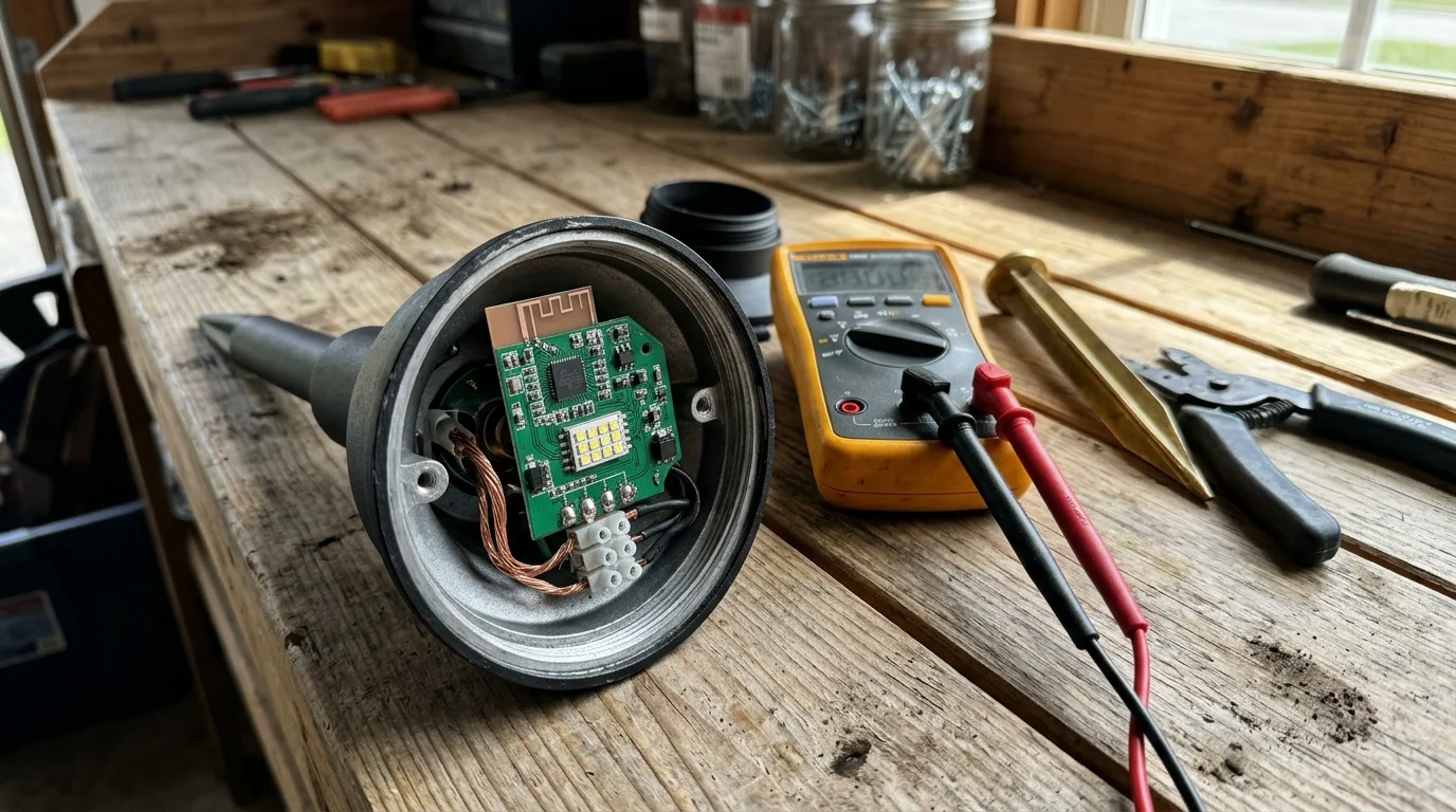
Smart fixtures incorporate internal microprocessors, radio transceivers, and digital dimming modules. These components draw standby power twenty-four hours a day, even when the luminaires emit zero light.
Devices built on the Matter smart home standard communicate across local Thread mesh networks to eliminate proprietary bridge dependencies. Thread border routers require line-powered mesh nodes to remain awake continuously to relay network packets.
A typical architectural LED path light consumes 4 to 5 watts while illuminated. However, its integrated Thread or Zigbee radio module draws an additional 0.5 to 0.8 watts of continuous standby power.
While 0.8 watts sounds negligible for an individual fixture, twelve border lights add nearly 10 watts of unmetered, constant parasitic drain across your line. That parasitic draw constantly saps electrical potential before you even account for light output.
Ignoring this radio load produces major math errors during transformer planning. The resulting voltage drop causes distant path lights to drop off your Thread network unexpectedly during peak brightness events.
Standard smart automation platforms register these offline nodes as unresponsive accessories. Sizing transformer smart garden layouts properly requires including both active illumination watts and continuous wireless transceiver loads.
Conduit-Free Driveway Routing and NEC Compliance
Installing landscape lighting alongside a 120-foot asphalt driveway without existing underground conduit introduces strict regulatory constraints. You cannot simply bury cable haphazardly beneath the turf and stay compliant with safety codes.
The National Electrical Code (NEC) governs low-voltage exterior lighting under Article 411. This code mandates that low-voltage landscape lighting operating circuits cannot exceed 30 volts AC or 60 volts DC under normal operating conditions.
Furthermore, secondary power circuits are legally capped at a maximum current output of 25 amperes per circuit. Sizing your transformer circuits within these boundaries protects your home from fire hazards caused by damaged exterior wiring.
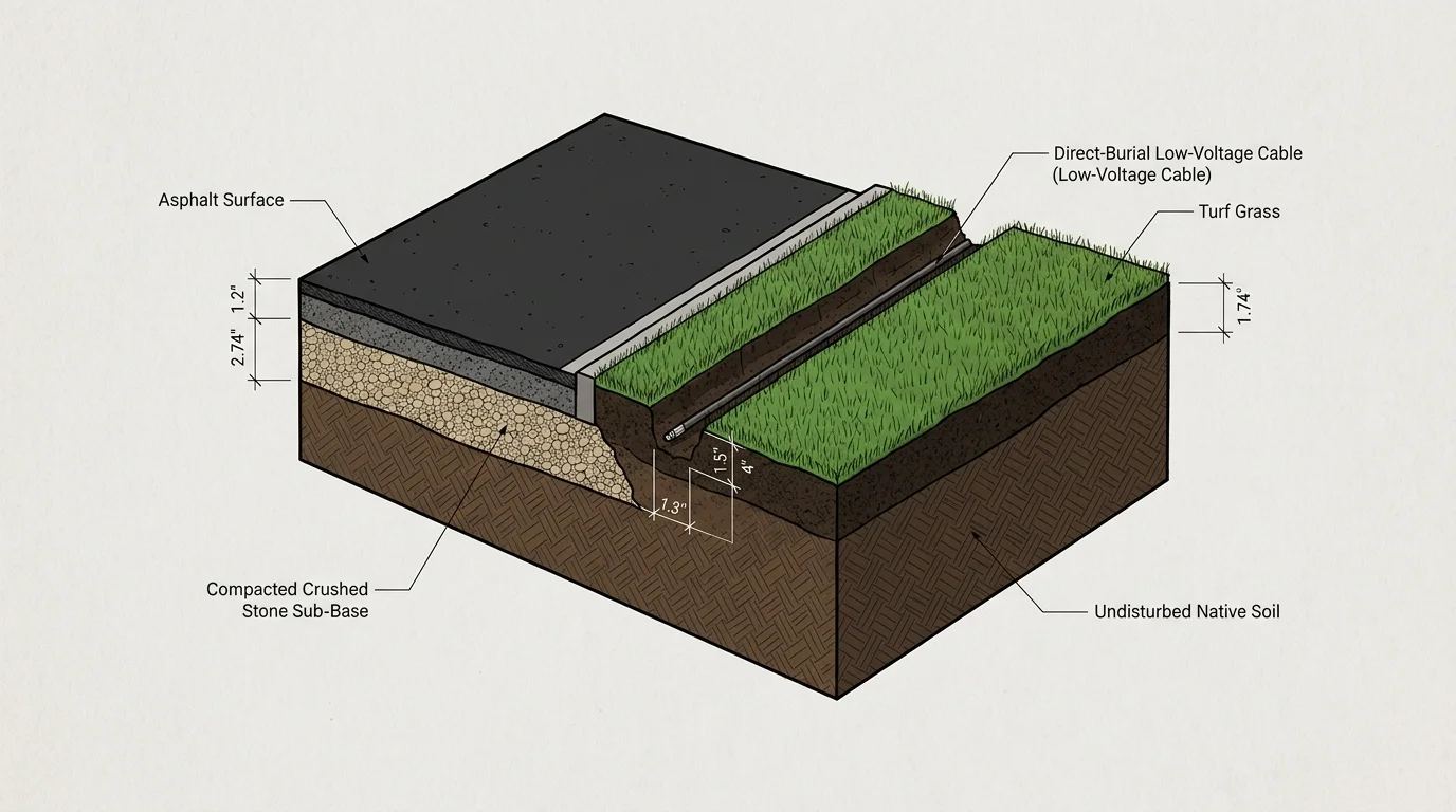
Burying direct-burial cable requires strict adherence to NEC Table 300.5. Low-voltage cables carrying 30 volts or less require a minimum burial depth of 6 inches in residential soil or turf.
The burial requirements change drastically if your wiring path ever crosses beneath a driveway or vehicular parking area. NEC Table 300.5 mandates a minimum burial depth of 18 inches underneath residential driveways unless you sleeve the wire inside rigid metal conduit.
Because your asphalt driveway lacks pre-installed conduit, crossing underneath it requires horizontal directional boring or saw-cutting. You can avoid this expensive disruption entirely by routing your cables exclusively through turf and mulched borders alongside the pavement.
Exterior power supply connections must also comply with NEC Article 210.8. All outdoor 120-volt convenience receptacles supplying your low-voltage transformer require Ground-Fault Circuit-Interrupter (GFCI) protection.
These exterior outlets must feature an in-use, weatherproof cover—commonly known as a bubble cover. This heavy-duty housing protects the transformer plug from direct rain exposure even while connected.
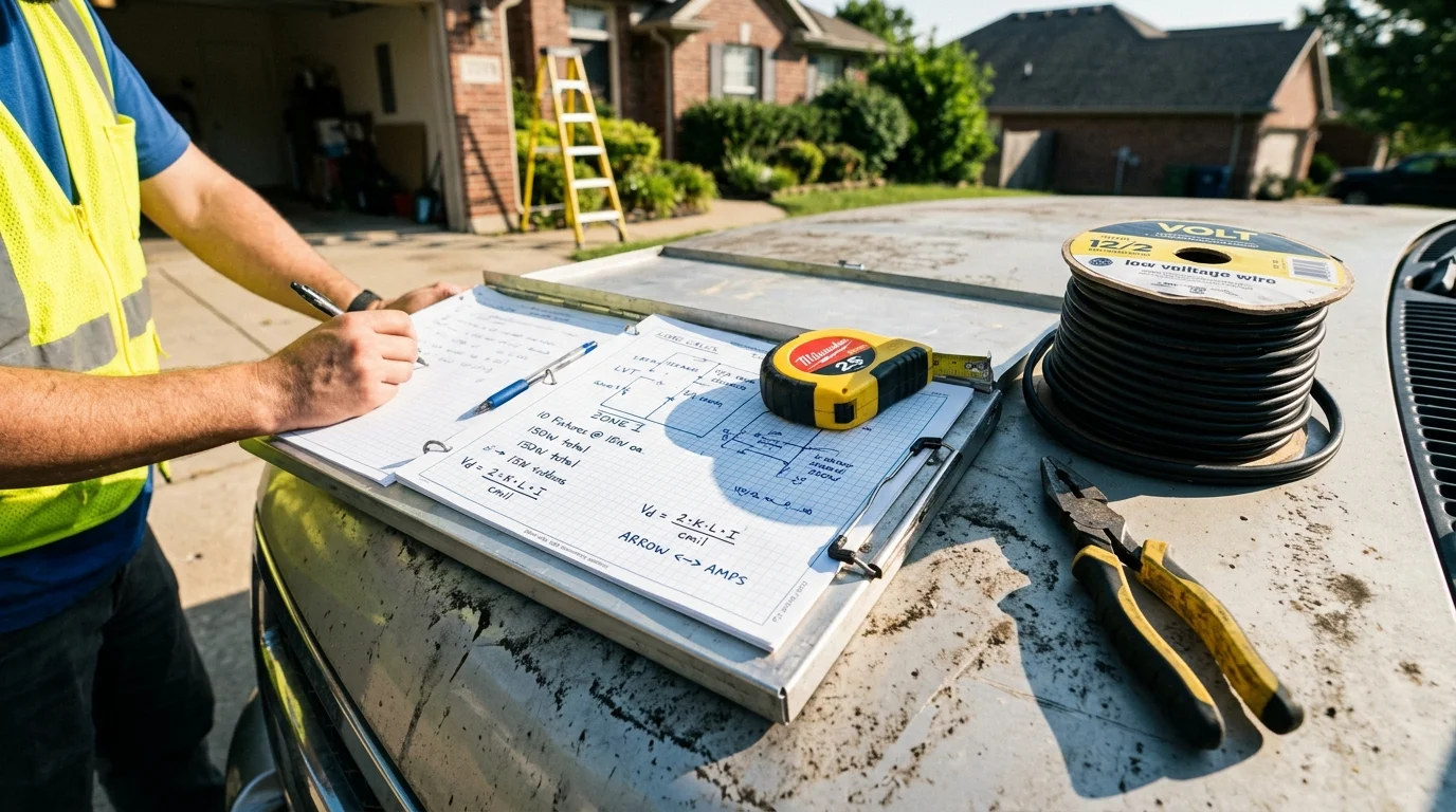
Step-by-Step Transformer Sizing: A 120-Foot Worked Example
Consider a suburban home with a straight, 120-foot asphalt driveway bordered by turf. In this real-world scenario, you want to install twelve low voltage smart landscape lighting path lights spaced ten feet apart.
You also plan to mount two smart accent spotlights near the street apron to illuminate your stone entrance pillars. The transformer mounts on the exterior wall of your attached garage next to a dedicated GFCI outlet.
Follow these specific calculation steps to establish your total electrical demand and determine correct wire sizing:
- Calculate the active illumination wattage for all planned fixtures. Twelve smart path lights at 5.0 watts each equal 60 watts. Two smart entrance spotlights at 8.0 watts each equal 16 watts, bringing your base illumination load to 76 watts.
- Add the continuous radio transceiver draw for Thread mesh connectivity. Fourteen total connected fixtures drawing 0.8 watts of standby transceiver power add 11.2 watts of constant load. Your adjusted system operating load equals 87.2 watts.
- Apply the 80% continuous-load safety rule required by electrical design standards. Divide 87.2 watts by 0.80 to determine your baseline transformer capacity. This calculation establishes a minimum transformer rating of 109 watts.
- Measure total circuit run distance from the garage transformer to the final entrance spotlight. The physical distance measures 120 feet, but accounting for transformer risers and underground slack brings total conductor length to 135 feet.
- Calculate total circuit amperage. Divide your 87.2-watt operating load by the nominal 12-volt system potential to yield a continuous current draw of 7.27 amperes.
- Determine round-trip cable resistance to calculate total voltage drop. Standard 12/2 AWG copper cable has a loop resistance of approximately 3.24 ohms per 1,000 feet, whereas thicker 10/2 AWG cable presents only 2.04 ohms per 1,000 feet.
- Calculate line voltage drop using 12/2 AWG wire: multiply 7.27 amperes by 3.24 ohms by 0.135 thousand feet. This configuration yields a severe drop of 3.18 volts.
- Subtract the 3.18-volt drop from a baseline 12.0-volt tap output. The final entrance lights would receive only 8.82 volts, causing immediate driver failure and network drops.
- Recalculate line drop using heavy-duty 10/2 AWG wire: multiply 7.27 amperes by 2.04 ohms by 0.135 thousand feet. The voltage drop decreases significantly to 2.00 volts.
When running 10/2 AWG wire, the final fixture receives 10.00 volts from a standard 12.0-volt tap. While this improves performance, it remains well below the safe 10.8-volt operating threshold for Thread transceivers.
Connecting this 10/2 AWG run to a multi-tap transformer set to the 14-volt secondary output tap completely eliminates the deficit. Subtracting your 2.00-volt line drop from a 14.0-volt baseline delivers 12.00 volts directly to the furthest fixture.
The first path light located 15 feet from the garage receives 13.78 volts. This value sits safely inside the fixture’s allowable 10.8V to 15.0V input tolerance window.
Therefore, this 120-foot driveway installation requires a multi-tap transformer rated for at least 150 watts paired with continuous 10/2 AWG direct-burial cable.

Selecting Multi-Tap Voltages and Cable Gauges
Selecting the correct copper wire gauge is your first line of defense against excessive voltage drop. Low-voltage landscape cables use American Wire Gauge (AWG) sizing, where smaller gauge numbers indicate thicker copper cores.
Direct-burial cables sized at 12/2 AWG feature two insulated 12-gauge copper conductors wrapped in a direct-burial rated PVC jacket. While 12/2 cable works well for compact patio gardens, long driveway runs demand 10/2 AWG or even 8/2 AWG wire.
Multi-tap transformers solve severe distance-related voltage drop by providing stepped secondary terminal outputs. Instead of offering only a fixed 12-volt output, multi-tap units provide terminal blocks labeled 12V, 13V, 14V, and 15V.
These stepped taps deliver higher output voltages to counteract anticipated line resistance. The higher initial voltage compensates for copper resistance so that distant fixtures receive optimal operating voltage.
However, you must exercise caution when utilizing boosted transformer taps. Delivering excessive voltage to nearby fixtures will permanently damage their internal microcontrollers.
- 12-Volt Secondary Tap: Ideal for compact lighting runs measuring under 50 feet with total circuit loads below 60 watts.
- 13-Volt Secondary Tap: Balances line drop on medium runs between 50 and 90 feet using standard 12/2 AWG direct-burial cable.
- 14-Volt Secondary Tap: Compensates for resistance across 100 to 160-foot runs like our asphalt driveway scenario when paired with 10/2 AWG cable.
- 15-Volt Secondary Tap: Reserved exclusively for runs exceeding 175 feet using 8/2 or 10/2 AWG cable where terminal fixtures suffer massive resistance loss.
Always verify the maximum voltage tolerance of your specific smart fixtures before energizing high-voltage taps. Most premium architectural smart lights tolerate up to 15.0 volts AC, but budget fixtures may burn out if input voltage exceeds 13.5 volts.
Use a digital multimeter to measure actual operational voltage at both the closest fixture and the final fixture on the circuit. Take this measurement at night while all fixtures run at 100 percent brightness.
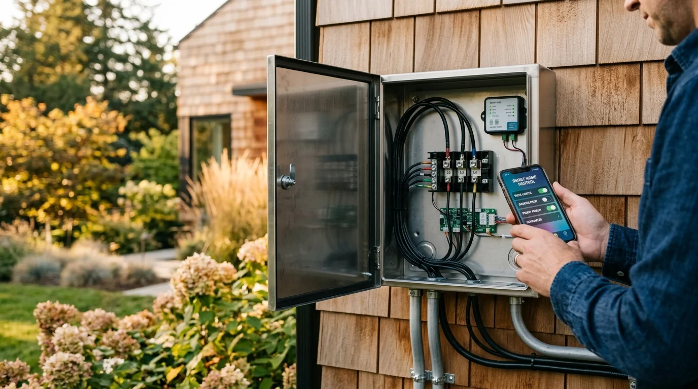
Smart Transformer Hardware and Ecosystem Integration
Choosing transformer hardware involves balancing output capacity, multi-tap terminal options, and smart ecosystem compatibility. Consumer landscape products often sacrifice terminal flexibility in favor of proprietary app integration.
For example, the Ring Smart Lighting 200-Watt Transformer retails around $99.99 MSRP and integrates smoothly into Alexa ecosystems through an Amazon Sidewalk bridge. It provides stepped 12V to 15V terminals, making it capable of handling extended runs.
Conversely, closed lighting solutions like Philips Hue Outdoor rely on proprietary 24-volt direct-current power supplies. Their 95-watt outdoor power supply retails for approximately $90 to $100 but uses specialized, thin cabling that restricts run distances to 115 feet.
Independent analysis from PCMag smart home testing highlights how closed outdoor lighting systems frequently struggle with hardware flexibility on larger suburban properties. Dedicated architectural multi-tap smart transformers solve these physical limitations by decoupling line voltage delivery from fixture automation.
| Transformer Model | Rated Capacity | Voltage Taps | Wireless Protocol | MSRP Price | Max Distance (100W Load) |
|---|---|---|---|---|---|
| Ring Smart 200W | 200 Watts | 12V, 13V, 14V, 15V | Ring Bridge / Sidewalk | $99.99 | 140 feet (10/2 AWG) |
| Philips Hue Outdoor 95W | 95 Watts | 24V DC Fixed | Zigbee / Matter via Bridge | $99.99 | 115 feet (Proprietary) |
| Volt Clad Pro 300W | 300 Watts | 12V, 13V, 14V, 15V | None (Requires Smart Plug) | $279.99 | 220 feet (10/2 AWG) |
| Kichler Smart Control 300W | 300 Watts | 12V, 13V, 14V, 15V | Wi-Fi / Bluetooth | $349.99 | 220 feet (10/2 AWG) |
| FX Luminaire Luxor 300W | 300 Watts | 14V Multi-Tap Internal | Wi-Fi / LAN | $749.99 | 300 feet (8/2 AWG) |
If you choose a professional multi-tap unit without native smart features, you can easily modernize it yourself. Pair the heavy-duty transformer with an outdoor smart plug rated for 15-amp inductive loads.
This hybrid setup provides clean multi-tap voltage boosting while integrating with Matter, Apple Home, or Home Assistant. Your smart home hub automates primary transformer power while individual Thread path lights manage color and zoning locally.
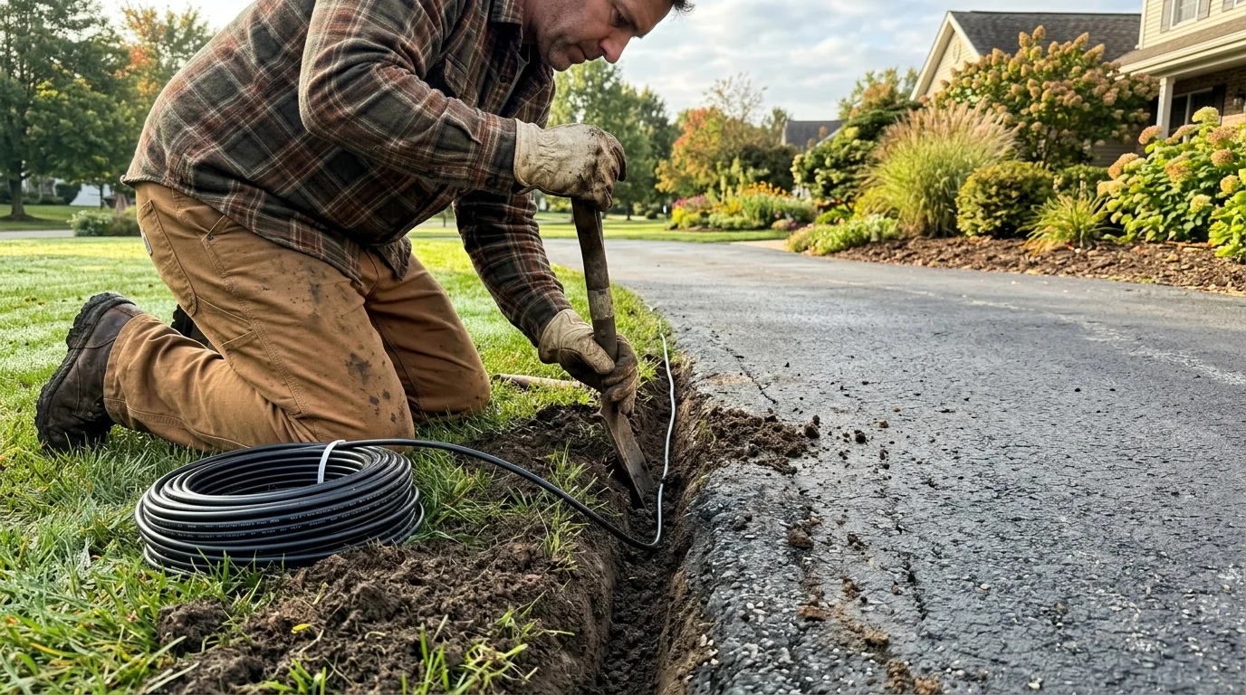
Trenching and Installation Strategies Without Cutting Asphalt
Trenching along an asphalt driveway requires careful planning to prevent accidental line cuts and winter frost heave. You must establish a continuous, protected path from your garage transformer down the entire boundary.
Begin by mapping your routing corridor along the turf edge directly adjacent to the asphalt shoulder. Keep your trench line 8 to 12 inches away from the pavement edge.
This offset protects your wiring from heavy vehicle tires that occasionally veer off the asphalt surface. It also prevents your trenching shovel from damaging the compacted aggregate base supporting your driveway edge.
- Contact your local utility locator service by dialing 811 at least three business days before excavating. Verify all underground gas, electrical, water, and fiber-optic utilities before breaking ground.
- Use a flat-edged landscape trenching spade or a motorized mechanical bed-edger to slice a narrow 7-inch-deep slot along the turf perimeter. A depth of 7 inches ensures full compliance with the NEC Table 300.5 6-inch direct-burial standard.
- Unspool your 10/2 AWG direct-burial cable along the trench line during the warmest part of the day. Warm sunlight relaxes the stiff PVC jacket, allowing the cable to lay flat without curling.
- Drop the cable into the bottom of the trench, ensuring no rocks, sharp gravel, or tree roots press directly against the protective sheath. Leave 12 inches of cable loop slack at every planned fixture location to facilitate easy servicing.
- Make your wire taps using waterproof, silicone-filled wire nuts or mechanical gel-capsules. Never use standard indoor twist-on wire connectors; exterior soil moisture rapidly corrodes exposed copper conductors.
- Backfill your trench halfway with native soil, tamp it firmly with your boots, and lay plastic underground electrical warning tape along the run. Complete the backfill to surface level and restore your turf.
If your driveway features concrete curbing or intersecting stone walkways, do not saw-cut the masonry. Instead, install a simple water-jet boring tool made from rigid PVC pipe attached to your garden hose to wash an opening beneath the slab.
This hydraulic tunneling method creates a clean, narrow channel beneath hardscapes in minutes. Once drilled, slide a protective PVC conduit sleeve through the tunnel and pull your low-voltage cable through smoothly.
Frequently Asked Questions
Why are my smart landscape lights turning on but showing offline in my smart home app?
When voltage drops below 10.8 volts, path lights often output dim light while their wireless microcontrollers freeze. Moving your circuit wire to a 13-volt or 14-volt transformer tap restores the voltage needed to power Thread and Zigbee radios reliably.
Can I connect both smart path lights and standard 12V halogen spotlights to the same transformer?
Yes, but you must calculate their power demands independently. Halogen lamps draw substantially higher wattage than LEDs and will drastically accelerate line voltage drop along extended wire runs.
How deep do I need to bury low-voltage lighting wire along my driveway?
According to NEC Table 300.5, direct-burial low-voltage cables carrying 30 volts or less require a minimum burial depth of 6 inches in residential turf. If your line passes beneath a vehicular driveway, you must bury it at least 18 inches deep unless sleeved inside rigid conduit.
What happens if I set my multi-tap transformer to 15 volts on a short lighting run?
Setting the transformer tap too high causes over-voltage at nearby fixtures. Supplying more than 15.0 volts to low-voltage LED drivers causes severe overheating, premature driver failure, and potential fire hazards.
Disclaimer: This article is for informational purposes only. Smart home devices involve electrical connections and data privacy. Always follow manufacturer instructions for installation. For complex wiring or HVAC work, consult a licensed professional.




2 Comments