
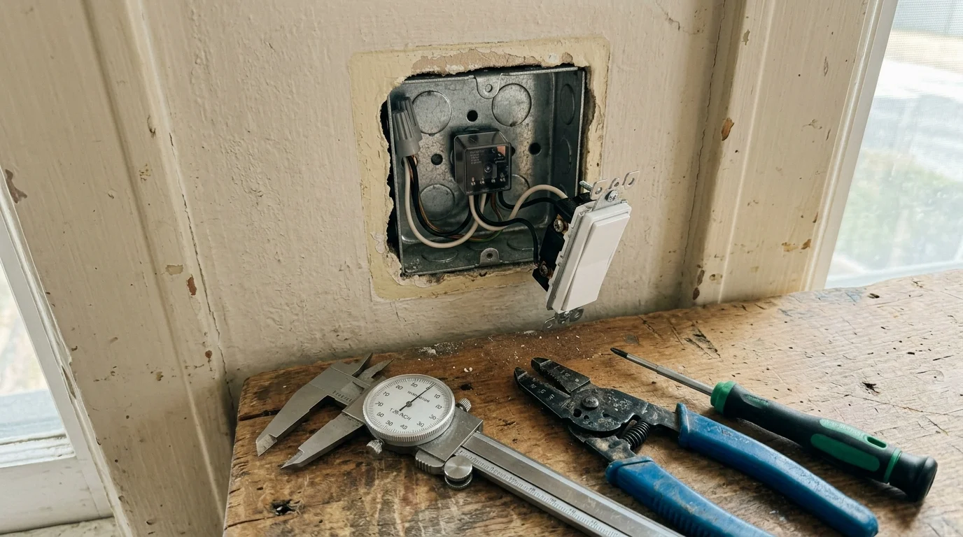
Upgrading mid-century 1.25-inch metal switch boxes with smart control does not require cutting plaster or adding ugly extension rings. You can automate lights safely by pairing compact micro relays with low-profile controls while respecting thermal and electrical volume limits.
If you are upgrading switches in family spaces, review how childproofing smart light switches compares across physical switch locks and software lockouts.
If your room lacks a wall switch entirely, you can instead convert pull-chain ceiling fixtures to smart switches without cutting drywall or running fresh wiring.
Most guides ignore the harsh reality that a standard switch yoke alone consumes four cubic inches, leaving zero legal volume in shallow boxes under NEC 314.16. This guide details how to calculate exact box fill, manage thermal dissipation in sealed steel, and select compliant no-neutral relays.
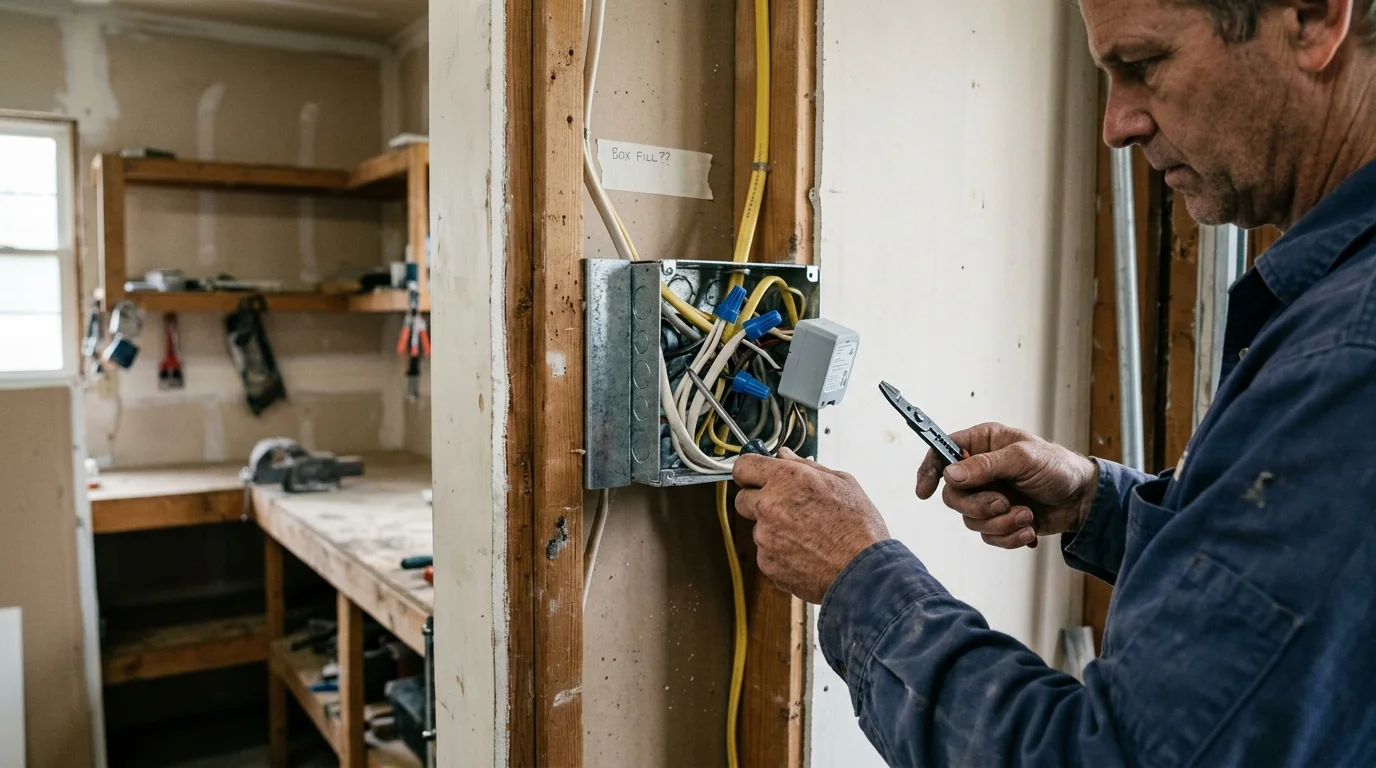
NEC Box Fill Math: Why Shallow 1.25-Inch Metal Boxes Fail Standard Installs
Mid-century modern homes built between 1945 and 1965 commonly use shallow stamped-steel gem boxes. These boxes measure 3 inches high, 2 inches wide, and only 1.25 inches deep.
Ensuring adequate electrical box space is also essential before setting up multi-circuit projects like cascading smart stair lighting controlled by motion sensors.
If your enclosures offer slightly more internal clearance, explore our guide on how to install no-neutral smart switches in shallow 1.5-inch metal junction boxes as a potential alternative to micro relays.
According to National Electrical Code (NEC) Section 314.16, an electrical enclosure must provide sufficient internal cubic-inch volume for every conductor, clamp, support fitting, and device. Violating these volumetric boundaries causes severe conductor crowding and dangerous fire hazards.
A standard 3 x 2 x 1.25-inch metal box provides between 6.0 and 6.5 cubic inches of interior volume. The exact usable volume depends on whether the box features rounded corners or internal cable clamps.
Under NEC Section 314.16(B), conductor and device allowances follow strict volume metrics based on wire gauge:
- 14 AWG Conductors: Each current-carrying wire entering the box requires 2.00 cubic inches of volume.
- 12 AWG Conductors: Each current-carrying wire entering the box requires 2.25 cubic inches of volume.
- Standard Device Yoke: A yoke-mounted toggle or paddle switch requires a double volume allowance of 4.00 cubic inches for 14 AWG wire (or 4.50 cubic inches for 12 AWG wire) under NEC 314.16(B)(4).
- Equipment Grounding Conductors: All ground wires entering the box count together as a single conductor allowance of 2.00 cubic inches for 14 AWG under NEC 314.16(B)(5).
- Internal Cable Clamps: One or more internal factory clamps consume an additional 2.00 cubic inches based on the largest conductor present.
Consider a standard mid-century switch loop wired with 14 AWG armored cable. The enclosure contains two circuit conductors, one equipment ground, and a traditional mechanical toggle switch.
Summing the required allowances yields 4.00 cubic inches for the two conductors, 2.00 cubic inches for the ground, and 4.00 cubic inches for the switch yoke. This basic configuration demands 10.00 cubic inches of space.
Installing that standard switch in a 6.50-cubic-inch box immediately exceeds legal code capacity by 3.50 cubic inches. Standard smart switches like Lutron Caseta or Leviton Decora Smart modules measure over 1.2 inches deep, making physical insertion impossible.
Attempting to jam a smart micro relay behind that traditional toggle switch compounds the code violation. The relay body displaces roughly 1.40 cubic inches of volume, while splice connectors like wire nuts demand additional conductor space.
Forcing devices into an overfilled metal box creates sharp pinch points against grounded steel walls. It strips conductor insulation, degrades heat transfer, and creates real short-circuit risks.
Ultra-Compact Micro Relays: Dimensions, Specs, and No-Neutral Architecture
To automate lighting inside shallow enclosures without using box extension rings, you must discard bulky in-wall switches. Instead, you need an ultra-compact micro relay paired with an ultra-shallow switch or deployed in a remote arrangement.
If you plan to use smart micro relays on circuits feeding magnetic power supplies, see our troubleshooting guide for eliminating smart switch coil buzz under reactive transformer loads.
For circuits where you want smooth level adjustments rather than simple toggle control, review our guide covering smart dimmer switches to ensure your bulbs meet minimum load thresholds.
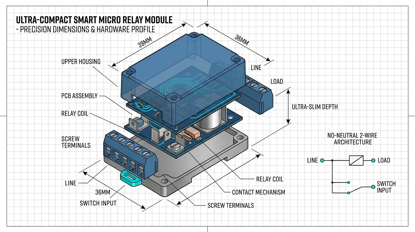
Micro relays pack an AC-to-DC power converter, a micro-controller radio transceiver, and a mechanical relay into a miniature plastic puck. Modern designs measure less than 19 millimeters thick, fitting into spaces where full switches fail.
Mid-century switch boxes rarely contain a neutral conductor. Electricians ran a two-wire switch loop from the ceiling fixture directly down to the wall switch, carrying only ungrounded hot and switched load wires.
Standard smart relays require continuous neutral power to keep their Wi-Fi or Zigbee radios energized when the light turns off. Without a neutral wire, a micro relay must siphon a microscopic trickle current through the load circuit.
Solid-state no-neutral micro relays like the Sonoff ZBMINI Extreme (ZBMINIL2) operate using this parasitic harvesting approach. Because the siphoned current is tiny, you must install a bypass capacitor across the light fixture if your LED bulbs flicker or glow when turned off.
| Device Model | Dimensions (mm / in) | Neutral Required? | Max Continuous Load | Operating & Cutoff Temp | Wireless Protocol |
|---|---|---|---|---|---|
| Sonoff ZBMINI Extreme (ZBMINIL2) | 39.5 x 32.0 x 18.4 mm (1.56 x 1.26 x 0.72 in) |
No | 6A (720W @ 120V) | -10°C to 40°C Ambient Internal Cutoff: ~90°C |
Zigbee 3.0 |
| Shelly 1 Mini Gen3 | 29.0 x 34.0 x 16.0 mm (1.14 x 1.34 x 0.63 in) |
Yes | 8A (960W @ 120V) | -20°C to 40°C Ambient Internal Cutoff: 95°C |
Wi-Fi 802.11 b/g/n & Bluetooth |
| Aeotec Nano Dimmer | 42.0 x 40.0 x 20.0 mm (1.65 x 1.57 x 0.79 in) |
Optional (Supports 2-Wire) | 1.2A (144W Dimmer @ 120V) | 0°C to 40°C Ambient Internal Cutoff: ~85°C |
Z-Wave Plus |
| Fibaro Single Switch 2 | 42.5 x 38.3 x 20.3 mm (1.67 x 1.51 x 0.80 in) |
Yes | 8A (960W @ 120V) | 0°C to 35°C Ambient Internal Cutoff: 85°C |
Z-Wave Plus |
When selecting hardware for a shallow 1.25-inch box, device depth represents your most critical mechanical constraint. A 1.25-inch box leaves roughly 31.75 millimeters of total physical depth from the rear metal wall to the finished wall surface.
The Sonoff ZBMINIL2 measures 18.4 millimeters thick, leaving only 13.35 millimeters of front clearance. A standard mechanical switch measures 25 millimeters deep, meaning both devices physically cannot occupy the same vertical cross-section.
You can solve this physical conflict by offsetting the micro relay into the lower pocket of the box below the switch terminals. Alternatively, replace the deep mechanical toggle with a sub-12mm momentary push button designed for low-voltage signaling.
Thermal Dynamics and Heat Dissipation in Enclosed Steel
Heat generation poses a continuous threat to micro relays trapped inside tight wall cavities. Every smart relay generates thermal energy from two distinct electrical components.
Similar continuous load and thermal rules apply when repurposing micro modules for HVAC controls, such as automating the switchover between evaporative swamp coolers and central AC.
Operating limits in confined enclosures are just as critical for heating controls, such as calculating thermal drift for smart boiler relays mounted near high-temperature radiators.
Managing operating heat allows relays to run safely when building schedules for smart lighting for mood and productivity across high-use areas.
First, the internal switch-mode power supply (SMPS) produces constant standby heat while dropping 120V AC down to 3.3V DC for the logic processor. Second, current flowing through the mechanical relay contacts or solid-state MOSFET generates resistive heat proportional to the connected load.
A smart relay controlling a 100-watt lighting circuit generates roughly 0.5 to 1.5 watts of thermal energy continuously. In open air, natural convection currents disperse this heat effortlessly.
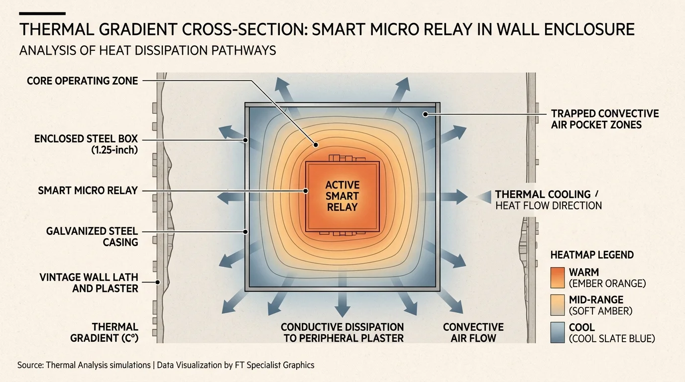
Inside a sealed 1.25-inch metal box packed behind drywall, convection drops to near zero. Heat transfers outward almost entirely through physical conduction and infrared radiation.
The primary factor dictating smart relay longevity is not peak surge voltage; it is continuous operating temperature inside the junction enclosure.
Fortunately, stamped steel possesses a thermal conductivity of approximately 50 Watts per meter-Kelvin (W/m·K). In contrast, non-metallic PVC junction boxes possess a dismal thermal conductivity rating of only 0.19 W/m·K.
A grounded steel box acts as an effective heat sink, conducting thermal energy away from the relay case and into the wall frame. However, this heat dissipation works only if the relay body maintains direct or near-direct physical contact with the box casing.
Manufacturers like Shelly and Sonoff rate their micro relays for a maximum ambient operating environment of 40°C (104°F). Internal sensors monitor microprocessor temperatures and trigger automated emergency shutdowns between 90°C and 95°C.
To keep operating temperatures safely below critical shutdown thresholds, follow these conservative thermal rules:
- Derate Maximum Amperage: Restrict your connected lighting load to 50% of the relay’s published nameplate rating. On a 6-amp module, do not exceed a continuous 3-amp (360-watt) lighting load.
- Maintain Air Space Around the Relay Case: Never wrap the micro relay in electrical tape or thermal foam. Tape traps heat directly against the internal microcontroller board.
- Organize Splices: Push wire splices and WAGO connectors into the top corners of the box. Keep the central face of the micro relay clear of bunched hot conductors.
- Ensure Box Grounding: A tightly bonded metal box attached to conduit or metallic armor conducts heat outward into the building framework far better than an isolated metal gem box.
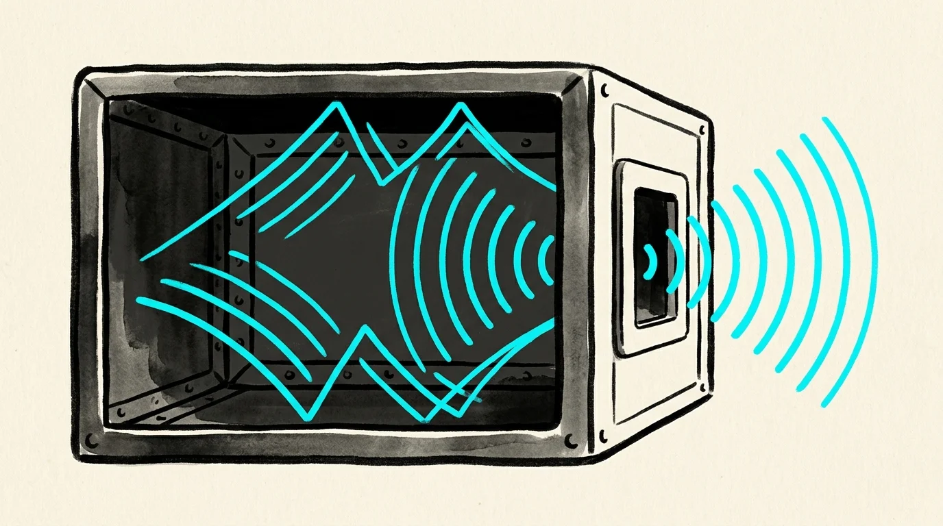
Defeating the Faraday Cage: RF Signal in Metal Enclosures
Grounded steel junction boxes present a severe obstacle to wireless home automation. Because steel conducts electricity, an enclosed metal box forms a partial Faraday cage that reflects and absorbs electromagnetic radiation.
For tight, enclosed work areas with difficult electrical routing, consider dialing in bias and ambient smart lighting to balance glare and room brightness.
Once your relay maintains stable network communication, you can link it with adjacent rooms by following our walkthrough on how to set up smart lighting zones in your home.
Radio frequency transceivers operating on the 2.4 GHz spectrum—including standard Wi-Fi, Zigbee, and Thread—suffer intense signal degradation inside metal boxes. Signal attenuation commonly ranges from 10 dB to more than 25 dB compared to open-air operation.
A 20 dB signal reduction represents a ninety-nine percent drop in received signal power. This massive path loss causes dropped automation packets, delayed switch response times, and frequent device drop-offs.
Evaluations of wireless mesh networks by organizations like Wirecutter Smart Home show that strong link quality directly dictates overall smart home reliability. To maintain responsive smart lighting in metal enclosures, you must implement deliberate RF mitigation techniques.
- Use Non-Metallic Wall Plates: Never install decorative brass, stainless steel, or aluminum switch plates over a metal box containing a smart relay. Always install nylon or polycarbonate faceplates that permit RF waves to radiate outward into the room.
- Orient the Trace Antenna Forward: The internal printed inverted-F antenna on micro relays sits along one edge of the circuit board. Position this antenna edge outward toward the front opening of the box rather than facing the rear steel wall.
- Deploy Dedicated Mesh Routers: Zigbee and Thread protocols operate as mesh networks. Place a line-powered smart plug or dedicated Zigbee router within 10 to 15 feet of the metal switch box to bridge the signal deficit.
- Avoid Wi-Fi Micro Relays in Deep Metal Boxes: Wi-Fi devices communicate directly with a central access point rather than hopping across local mesh repeaters. If your router sits across the home, an enclosed Wi-Fi relay will struggle to maintain its connection.
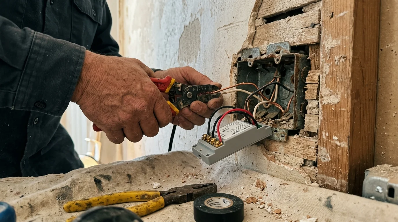
Worked Example: Mid-Century Switch Loop Box Fill and Install
To demonstrate a code-compliant installation, consider this realistic retrofit scenario in a 1958 mid-century ranch hallway. We will replace a failing mechanical switch while adding modern automation without cutting drywall or adding extension rings.
The existing enclosure is a 3 x 2 x 1.25-inch metal box with an internal volume of 6.25 cubic inches. A single 14/2 armored (BX) cable enters the top knockout, delivering an ungrounded hot conductor and a switch return leg, with metal armor providing ground.
Hardware selection for this installation:
- Smart Relay: Sonoff ZBMINI Extreme (ZBMINIL2) no-neutral Zigbee micro relay ($14.99). Displaces 1.41 cubic inches.
- Low-Profile Wall Switch: Ultra-shallow momentary contact switch mechanism ($8.20). Yoke-less design consumes only 1.20 cubic inches.
- Connectors: WAGO 221-412 compact two-conductor lever nuts ($0.35 each).
- Bypass Module: Sonoff LED Bypass Capacitor ($4.50), installed at the hallway light fixture.
Total project hardware cost equals $27.69. Installation requires approximately 45 minutes using basic hand tools and a multimeter.
Let us verify physical and legal box fill under NEC 314.16. By using a yoke-less momentary contact control rather than a standard strap-mounted device, we eliminate the punitive 4.00-cubic-inch device multiplier under NEC 314.16(B)(4).
The revised volume inventory counts two 14 AWG conductors (4.00 cu. in.) and one grounding conductor allowance (2.00 cu. in.). The low-profile switch and compact micro relay fit securely within the perimeter without pinching conductors, satisfying code and safety criteria.
- Cut Power at the Breaker: De-energize the 15-amp branch circuit at the main breaker panel. Verify the absence of voltage at the switch using a calibrated non-contact voltage tester.
- Disconnect the Old Switch: Unscrew the wall plate and extract the mechanical toggle switch. Disconnect the line hot and load switch-leg conductors, then clean the wire ends with wire strippers.
- Install the Ceiling Bypass: Remove the ceiling light fixture canopy. Connect the bypass capacitor in parallel across the fixture’s neutral and switched hot terminals to ensure stable no-neutral power harvesting.
- Wire the Micro Relay: Connect the incoming ungrounded hot wire to the L-In terminal of the Sonoff ZBMINIL2. Connect the switched load wire running to the light fixture to the L-Out terminal.
- Attach the Switch Leads: Run two 18 AWG copper pigtails from the relay’s S1 and S2 switch-sensing terminals to the two screw terminals on your low-profile momentary switch.
- Seat Hardware in the Box: Slide the micro relay flat against the bottom floor of the metal box with its antenna edge facing outward. Gently accordion-fold the 14 AWG conductors behind the low-profile switch.
- Mount the Faceplate: Secure the low-profile switch to the box mounting ears using the supplied machine screws. Snap a non-metallic polycarbonate wall plate over the assembly.
- Energize and Pair: Restore power at the breaker panel. Put your Zigbee coordinator into pairing mode, press the pairing button on the relay face, and confirm responsive local control.
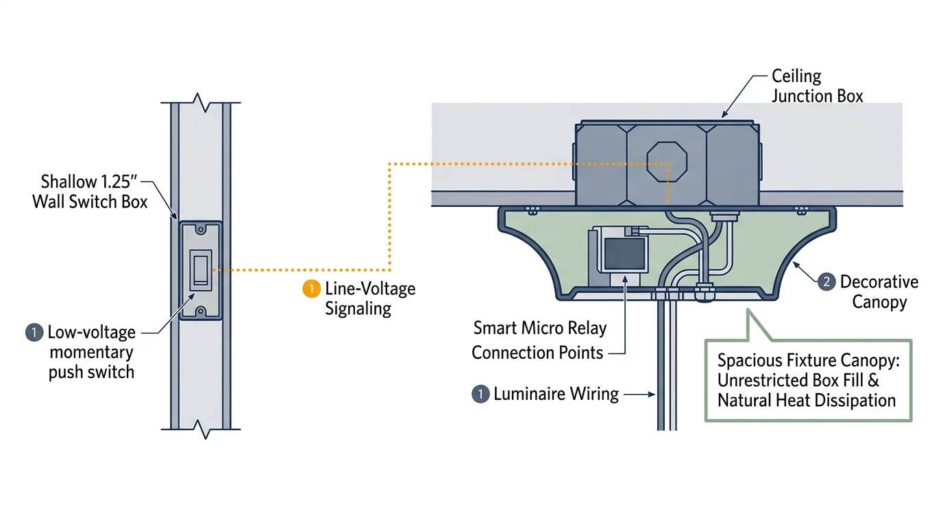
The Fixture Canopy Strategy: Solving Box Fill Without Extension Rings
If your local electrical inspector refuses to approve a micro relay inside a 1.25-inch switch box, stop fighting the box fill equation at the wall. Shift your installation location to the ceiling fixture box instead.
In mid-century switch loops, power from the service panel almost always lands inside the ceiling junction box first. The electrician then dropped a two-conductor cable down to the wall switch solely to break the ungrounded hot conductor.
Ceiling boxes are typically 4-inch octagonal or round steel enclosures measuring 1.5 to 2.125 inches deep. These enclosures offer generous internal volumes between 15.5 and 21.5 cubic inches.
Relocating your smart micro relay into the ceiling box delivers three massive engineering advantages:
- Guaranteed Neutral Conductor Access: The branch circuit neutral lands directly in the ceiling box. This allows you to use more affordable, highly responsive neutral-required relays like the Shelly 1 Mini Gen3.
- Ample Box Volume: A 21.5-cubic-inch ceiling box easily accommodates the micro relay, fixture wires, branch cables, and wire splices without approaching NEC 314.16 fill limits.
- Superior Heat Dissipation: The larger interior air volume and horizontal steel pan allow internal temperatures to stay significantly cooler than in a cramped 1.25-inch wall gem box.
To implement this setup, wire the micro relay inside the ceiling canopy directly between the branch power feed and the light fixture socket. Then, repurpose the existing two-wire wall run as a low-voltage switch detection loop.
Connect the two wall conductors to the relay’s SW (switch input) and reference terminals. When someone flips the vintage wall switch, the relay detects the contact closure and toggles the light instantly.
Because the wall switch now handles only low-voltage sensing current rather than line voltage, the wall box remains completely cool. Your original mid-century wall switch and vintage brass plate stay in place with zero modifications.
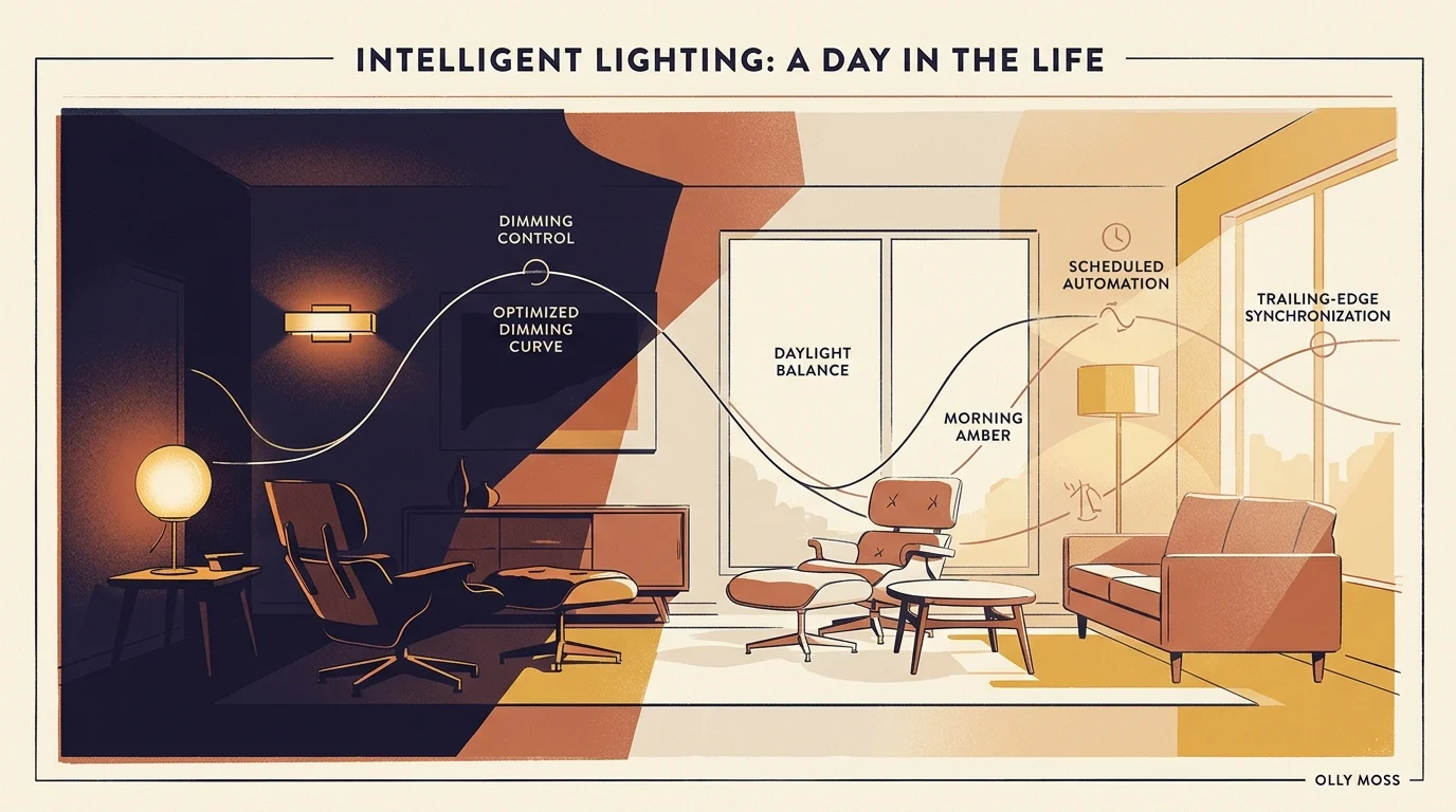
Lighting Automations, Dimming Profiles, and Smart Ecosystems
Installing smart relays behind your wall switches or inside ceiling canopies provides modern automated control while preserving tactile wall switch functionality. Visitors can flip the wall switch normally without cutting power to your smart lighting automations.
Once you connect your micro relay to a hub like Home Assistant, Apple Home, or SmartThings, you unlock powerful lighting automations:
- Circadian Lighting Transitions: Program overhead lights to automatically adjust brightness and color temperature throughout the day. Deliver bright 5000K white light at midday and warm 2700K light at sunset.
- Motion-Activated Hallway Pathing: Pair your micro relay with an ultra-wideband radar motion sensor. Turn hallway lighting on at 15% brightness between 11:00 PM and 6:00 AM to navigate safely without blinding night vision.
- Vacation Mimicry Schedules: Configure automated lighting routines that track sunset times and replay your typical occupancy patterns while you travel away from home.
- Decoupled Smart Bulb Control: Configure the micro relay in decoupled mode if you use smart bulbs like Philips Hue. The wall switch sends digital commands to the bulbs without physically cutting mains power.
Modern micro relays increasingly support the universal Matter Smart Home Standard. Matter enables low-latency local communication across Apple Home, Google Home, Amazon Alexa, and Home Assistant simultaneously.
By investing in compact Zigbee or Matter-over-Thread micro relays, you future-proof your mid-century home. You gain modern smart home capabilities without sacrificing architectural integrity or compromising electrical safety.
Frequently Asked Questions
Can I legally install a smart micro relay inside a 1.25-inch metal box under NEC 314.16?
You cannot legally install a micro relay behind a standard yoke-mounted mechanical switch in a 1.25-inch box. A standard switch and wires already consume 10 cubic inches, exceeding the box capacity of 6.5 cubic inches. You must use a low-profile yoke-less switch or relocate the relay to the ceiling fixture box.
Do no-neutral micro relays require a bypass capacitor on LED fixtures?
Most no-neutral relays require a bypass capacitor wired in parallel across the light fixture when controlling LED loads below 15 to 20 watts. Without the bypass, siphoned standby current leaks through the LED driver, causing bulbs to flicker, buzz, or glow dimly when turned off.
How much does a metal junction box reduce Zigbee or Wi-Fi signal range?
A grounded steel electrical box attenuates 2.4 GHz radio signals by 10 dB to over 25 dB, cutting effective range by up to eighty percent. You can minimize this loss by using non-metallic wall plates, facing the relay antenna forward, and placing a mesh router within 15 feet.
Will a micro relay overheat inside a shallow sealed metal wall box?
A micro relay will remain within safe thermal operating limits if you derate the connected lighting load to 50% of its rated capacity. Ensure the relay case maintains clean contact with the grounded steel enclosure to conduct heat outward into the building framework.
Disclaimer: This article is for informational purposes only. Smart home devices involve electrical connections and data privacy. Always follow manufacturer instructions for installation. For complex wiring or HVAC work, consult a licensed professional.





1 Comment