
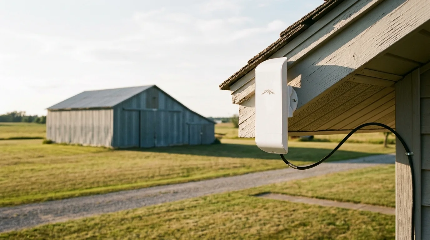
Securing your detached metal equipment barn requires reliable video data transmission across 300 feet of open yard. Standard mesh routers fail completely because corrugated steel walls reflect and absorb radio frequencies.
Once the bridge is active, you can securely monitor your home security remotely to check live barn footage without relying on costly third-party cloud plans.
Corrugated steel introduces up to 40 dB of signal attenuation, effectively locking camera data inside a Faraday cage. Mounting an exterior directional Point-to-Point Wi-Fi bridge bypasses this metal barrier without requiring an expensive trenching project.
This setup provides a high-throughput, low-latency link directly to your house network video recorder. You preserve full 4K frame rates while eliminating the electrical ground loops common in long copper cable runs.
The Physics of Metal Barn RF Attenuation
Corrugated steel siding and metal roofing act as electromagnetic shields. When radio waves encounter sheet steel, the conductive material reflects the majority of the signal back into space.
Homeowners managing broad rural properties should also look into mapping Thread mesh topologies across large ranch homes to keep smart sensors communicating around challenging architectural layouts.
Standard 2.4 GHz and 5 GHz wireless frequencies experience between 25 dB and 40+ dB of signal attenuation when passing through metal walls. This drastic loss leaves connected devices starved for throughput.
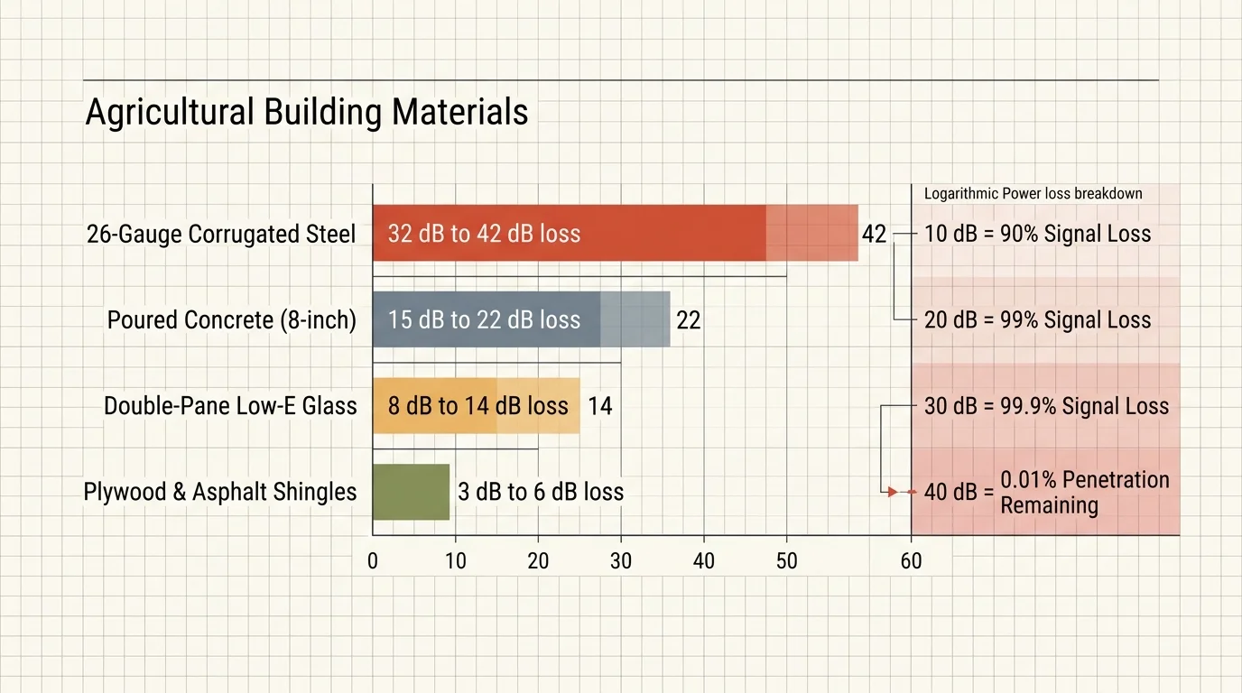
Decibels operate on a logarithmic scale. A 10 dB loss cuts your transmitted signal power by 90%, while a 20 dB loss eliminates 99% of that energy.
When attenuation reaches 30 dB, 99.9% of the radio signal vanishes. At 40 dB of attenuation, only 0.01% of the original signal penetrates the building interior.
Common agricultural building materials attenuate radio frequencies at varying rates:
- Standard 26-gauge corrugated steel cladding: 32 dB to 42 dB loss
- Plywood sheathing with asphalt shingles: 3 dB to 6 dB loss
- Poured concrete foundations (8-inch thickness): 15 dB to 22 dB loss
- Double-pane Low-E glass windows: 8 dB to 14 dB loss
- Clear, open air across a 300-foot span: roughly 86 dB of free-space path loss at 5 GHz
Attempting to broadcast Wi-Fi from inside your home to an access point inside a pole barn turns the structure into a Faraday cage. Your cameras will suffer constant dropped frames and connection dropouts.
To eliminate this barrier, you must place your wireless transceivers on the exterior of both structures. Exterior mounting guarantees an unobstructed line of sight and prevents metal siding from disrupting your camera streams.
Copper Trenching Versus Wireless Bridging at 300 Feet
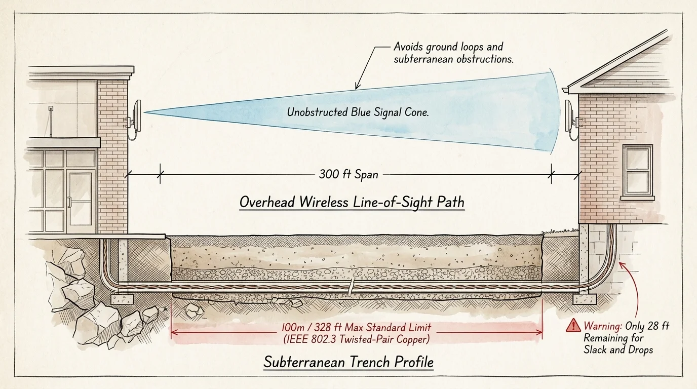
Running copper cable directly between two buildings creates significant mechanical and electrical hurdles. The IEEE 802.3 standard limits twisted-pair copper Ethernet runs to 100 meters, which equals 328 feet.
If you need early vehicle alerts across wide property boundaries without burying cables, consider pairing your network with long-range 915MHz LoRa beam sensors along the perimeter.
A 300-foot straight-line run between buildings leaves you with only 28 feet of allowable cable slack. Vertical drops down exterior walls and interior routing to your equipment rack quickly exceed that ceiling.
Exceeding the 328-foot limit causes signal degradation, increased packet retries, and Power over Ethernet (PoE) voltage drops. Your cameras may boot up intermittently or reboot whenever night-vision infrared LEDs turn on.
Digging a trench also demands substantial labor and regulatory compliance. The National Electrical Code (NEC) Table 300.5 mandates specific burial depths for outdoor electrical wiring.
- Rigid nonmetallic conduit (Schedule 40 or 80 PVC): 18 inches minimum cover depth
- Direct-burial rated underground cable without conduit: 24 inches minimum cover depth
- Conduit routed under commercial or heavy-vehicle driveways: 24 inches minimum cover depth
Meeting these depth requirements means renting a mechanical trencher and avoiding underground water lines or septic pipes. Rocky, clay-heavy, or frozen ground compounds the physical expense.
Detached outbuildings also introduce severe ground-loop hazards when connected via copper data cables. Your house and detached barn operate on separate electrical subpanels, each tied to independent earth grounding electrodes.
Ground potential differences between two separate structures can send equalization currents through the shield of an Ethernet cable, damaging network hardware and creating fire hazards.
When lightning strikes nearby, ground potential differences between the structures force high currents through your copper Ethernet cable. This surge frequently destroys connected network switches, NVRs, and camera sensors.
A directional Point-to-Point (PtP) wireless bridge provides complete galvanic isolation. You sever the physical electrical link between buildings entirely, eliminating ground loops while maintaining gigabit data speeds.
For additional insights on securing outdoor outbuildings with modern hardware, consult PCMag’s smart home security evaluations for testing data on perimeter network devices.
Calculating Camera Bandwidth and Bridge Capacity
Sizing your wireless bridge requires calculating the continuous throughput generated by your barn camera array. Security cameras transmit continuous video streams that consume fixed amounts of local bandwidth.
Implementing edge AI confidence tuning and polygonal masking prevents roaming livestock and windblown tree branches from triggering unneeded network traffic spikes.
You can mitigate weather-related bandwidth spikes by properly configuring motion detection zones to mask out swaying trees and rain glare.
Modern IP cameras use video compression codecs to minimize data rates. High Efficiency Video Coding (H.265) reduces required bandwidth by 40% to 50% compared to legacy H.264 compression without sacrificing image clarity.
Frame rates also dictate continuous bitrates. While cinema runs at 24 frames per second (fps), security cameras deliver fluid, actionable motion evidence at 15 fps to 20 fps.
The table below outlines continuous bandwidth consumption across common security camera resolutions using modern H.265 compression protocols at 15 fps.
| Camera Resolution | Video Compression | Bitrate Per Camera | 4-Camera Array Total | 8-Camera Array Total |
|---|---|---|---|---|
| 1080p (2 Megapixel) | H.265 (Main Profile) | 2.0 Mbps | 8.0 Mbps | 16.0 Mbps |
| 2K / 4MP (1440p) | H.265 (Main Profile) | 4.0 Mbps | 16.0 Mbps | 32.0 Mbps |
| 4K / 8MP (2160p) | H.265 (Main Profile) | 8.0 Mbps | 32.0 Mbps | 64.0 Mbps |
| 12MP Panoramic | H.265 (Main Profile) | 12.0 Mbps | 48.0 Mbps | 96.0 Mbps |
Video streams do not stay perfectly flat during operation. Nighttime scenes introduce digital sensor noise that can inflate video bitrates by 30% to 50% as compression algorithms process the grain.
A four-camera 4K array producing a nominal 32 Mbps can surge to 48 Mbps during a nighttime rainstorm. You must size your wireless bridge link to handle these baseline spikes effortlessly.
Entry-level 5 GHz directional bridges provide 150 Mbps to 450 Mbps of real-world TCP throughput over 300 feet. This throughput offers a massive 5x to 10x safety headroom above your camera array’s peak demands.
Hardware Selection for Point-to-Point Links
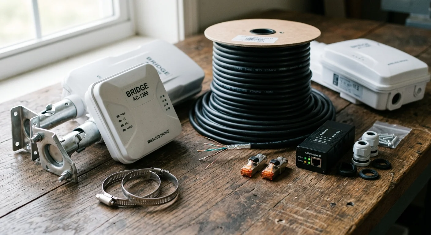
A dedicated bridge link consists of two matched directional transceivers configured as an access point and a station. Unlike omnidirectional home Wi-Fi antennas, directional bridges concentrate radio energy into a focused beam.
To keep detached outbuilding devices isolated from your primary computers, place the bridge link and barn subnet on a dedicated smart home guest network.
For remote sheds lacking dependable mains electricity, pair your switch with an off-grid camera system featuring battery backup to keep video feeds operating during outages.
Operating on the 5 GHz band keeps your bridge traffic clear of common 2.4 GHz interference generated by farm equipment sensors and consumer smart devices. Directional 5 GHz beams maintain narrow broadcast widths that do not pollute residential Wi-Fi channels.
Several commercial-grade bridge units deliver outstanding reliability across rural properties:
- Ubiquiti NanoStation Loco 5AC: Delivers up to 450 Mbps real throughput; compact form factor; powered by 24V passive PoE; requires external PoE injectors.
- TP-Link Pharos CPE710: Features a 23 dBi directional dish antenna; withstands severe weather; delivers up to 867 Mbps link speeds over long distances.
- EnGenius EnStation5-AC: Provides an integrated 19 dBi directional antenna; features IP55-rated weatherproofing; supports 802.3af PoE input directly.
Inside the barn, you need an unmanaged PoE switch to power both the bridge radio and your cameras. Equipment barns experience extreme temperatures, dust, and humidity that destroy standard office-grade network switches.
Select a hardened, industrial-rated PoE switch with an operating range of -40°F to 167°F. Ensure the switch delivers IEEE 802.3at (PoE+) power with a total power budget exceeding your cameras’ combined wattage by at least 25%.
Review comprehensive outdoor surveillance infrastructure guides at Wirecutter’s smart home reviews to compare weatherproof camera build qualities and mount designs.
Step-by-Step Exterior Mounting and Alignment
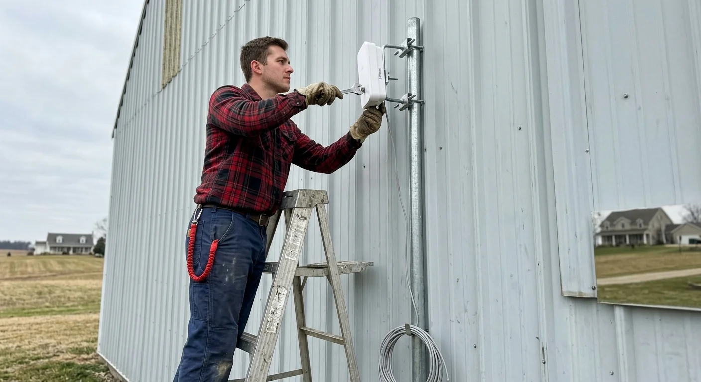
Mounting your directional radios correctly ensures maximum throughput and prevents signal dropouts caused by weather or structural movement. Follow these sequential installation steps to establish your bridge.
- Establish Line of Sight: Mount both bridge radios at least 10 to 12 feet above the ground on the exterior fascia or gable ends of each structure. Ensure no tree branches, farm equipment booms, or storage piles intersect the visual path between the two points.
- Calculate Fresnel Zone Clearance: Radio signals travel in an elliptical football-shaped pattern known as the Fresnel zone. At a 300-foot distance on 5 GHz, maintain at least 2.5 feet of clear radial space around the visual center line to avoid ground reflections.
- Secure Exterior Mounting Brackets: Attach rigid J-pole mounts to your building exterior using heavy-duty lag bolts anchored into solid structural framing. Do not attach mounts solely to thin sheet metal siding, as wind vibration will destabilize your antenna alignment.
- Route Shielded Cable: Run outdoor-rated, UV-resistant shielded Cat6 (STP) cable from the exterior radio into the building interior. Drill your entry hole through the metal siding with a downward outward angle, and bend a mechanical drip loop into the cable before entry.
- Seal the Penetration: Pack the siding penetration hole thoroughly with exterior-grade polyurethane or silicone sealant to prevent water infiltration and insect nesting. Fit an outdoor grommet or cable gland over the penetration for added protection.
- Perform Antenna Alignment: Power both units using their respective PoE injectors and set the house radio to Access Point PtP mode and the barn radio to Station PtP mode. Use the built-in LED signal indicators or the web management interface to align the directional beams.
- Lock Down Azimuth and Elevation: Tighten the mounting bracket hardware once your received signal strength indicator (RSSI) reads between -50 dBm and -60 dBm. Avoid signal levels hotter than -45 dBm, as over-driving the radio receiver can cause packet distortion.
Barn-Side PoE Distribution and Grounding Architecture
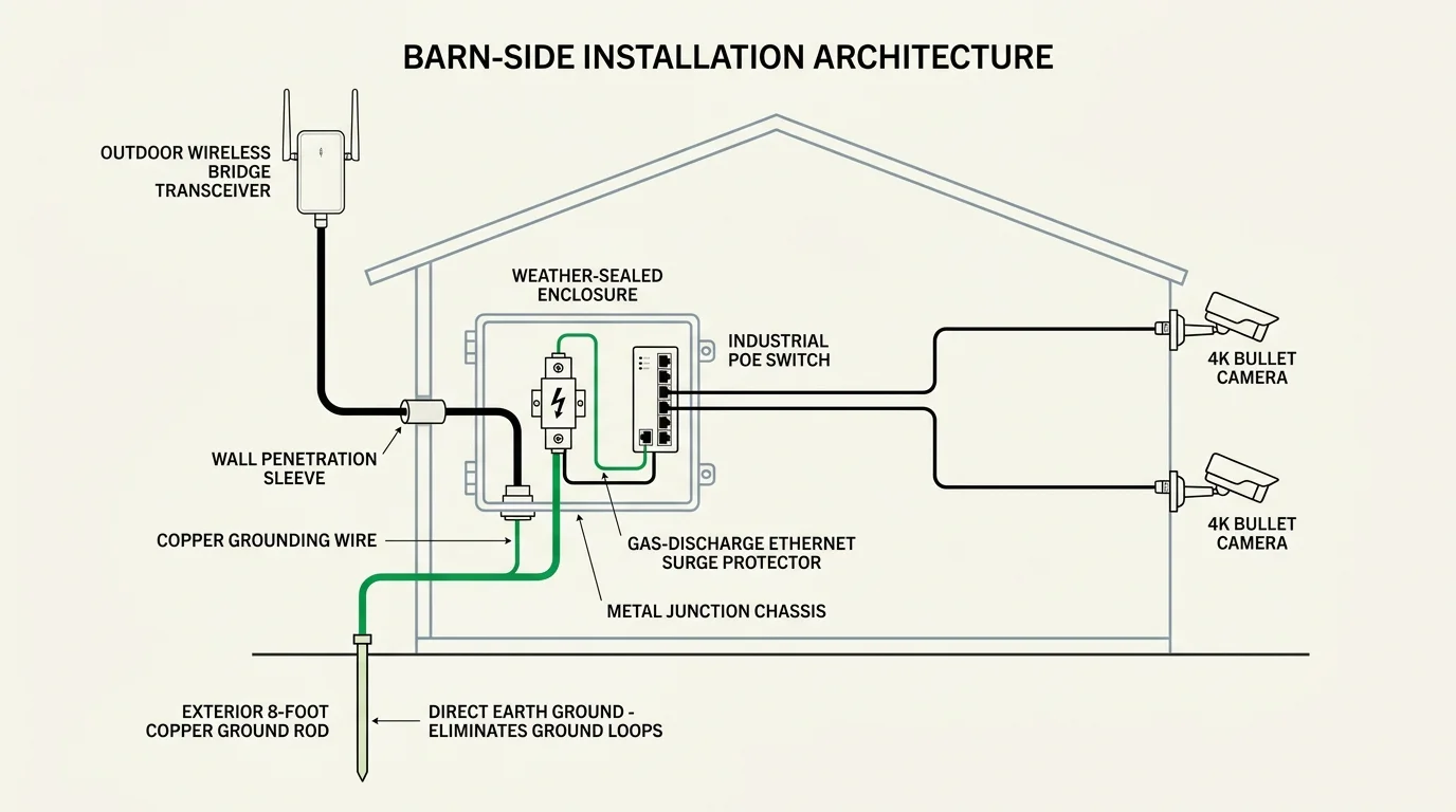
The exterior bridge radio on the barn must hand off its data connection to your interior camera distribution hardware. This transition point requires robust electrical protection to guard against static discharges.
Outdoor cables running down metal siding accumulate static charges from windborne dust and ambient storm clouds. Install an outdoor-rated Ethernet surge protector, such as the Ubiquiti ETH-SP-G2, right where the cable enters the barn.
Bond the surge protector’s ground lug directly to the building’s electrical service ground or metal frame using 14 AWG solid copper wire. This low-impedance path shunts transient energy safely into the earth before it reaches your switch.
From the surge protector, run standard Cat6 cable into your barn’s hardened PoE switch. This switch will supply power and data to your security cameras over individual Cat6 runs.
Plan your barn-side cable runs along interior purlins or inside PVC conduit to protect the jackets from rodents. Barn mice and squirrels will chew exposed network wiring, causing intermittent shorts.
Connect your barn-side network switch and PoE injectors to a dedicated line-interactive Uninterruptible Power Supply (UPS). Agricultural subpanels experience voltage sags and surges when heavy motors, air compressors, or welders start up.
A 750VA UPS cleans this incoming power, absorbs electrical noise, and keeps your barn cameras running during brief power blinks. Your recording streams will remain unbroken even during localized circuit trips.
Complete 300-Foot Metal Barn Worked Example
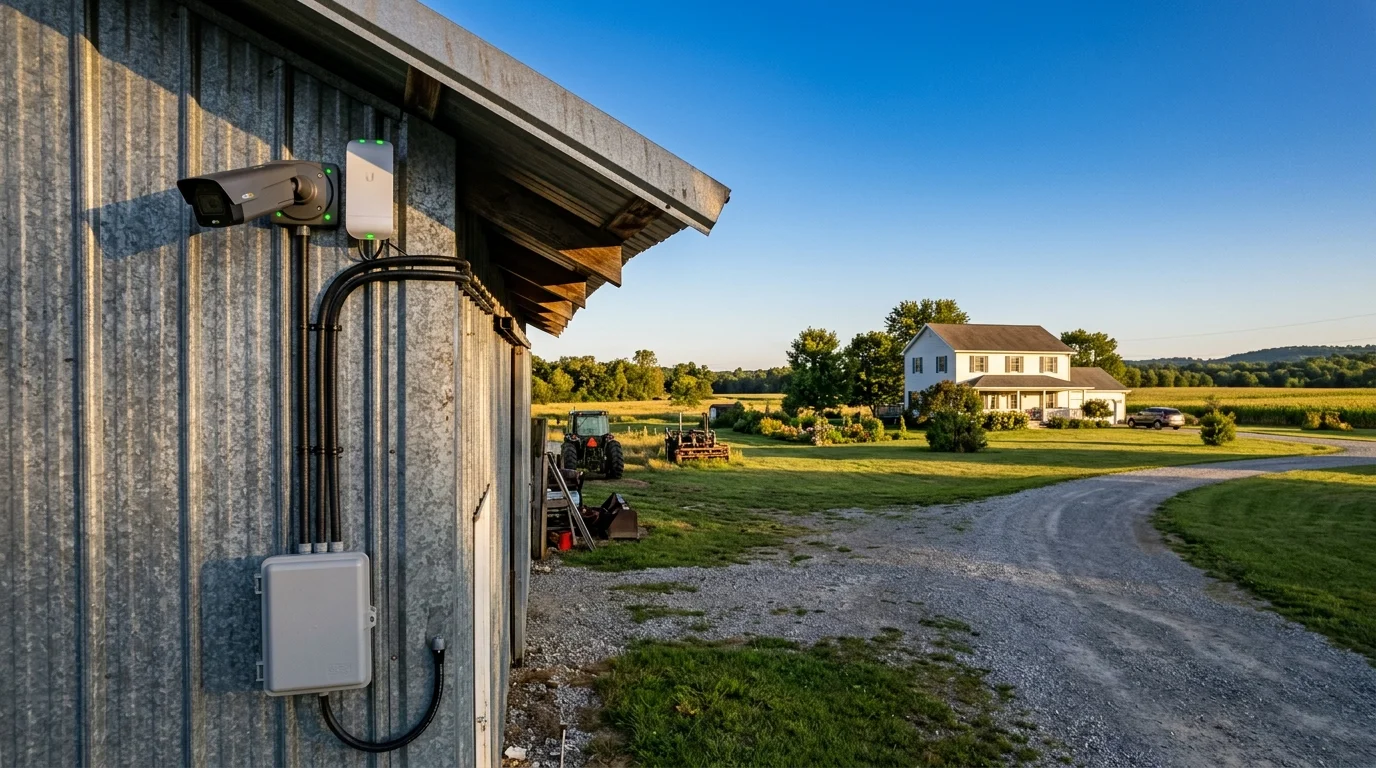
This worked scenario details a functional network deployment linking a residential house to a detached 40×60-foot pole barn located 300 feet away across a gravel driveway. The objective is streaming four 4K security cameras back to a basement NVR.
The bill of materials provides exact real-world component costs for the installation:
- Ubiquiti NanoStation Loco 5AC (pair): $98.00 ($49.00 each)
- Ubiquiti POE-24-12W-G 24V Gigabit PoE Injectors (pair): $28.00 ($14.00 each)
- TP-Link TL-SG105PE 5-Port Gigabit PoE+ Switch (65W budget): $59.99
- Ubiquiti ETH-SP-G2 Ethernet Surge Protectors (pair): $30.00 ($15.00 each)
- Vertical Cable 250-foot spool Shielded CMX Outdoor Cat6: $68.00
- Universal J-Pole outdoor antenna mounts (pair): $34.00 ($17.00 each)
- APC Back-UPS 600VA Line-Interactive Battery Backup: $74.99
- Miscellaneous grounding wire, hardware, and silicone sealant: $22.50
- Total Network Infrastructure Cost: $415.48
Network configuration uses static IP addressing to ensure the bridge operates as a transparent Layer 2 Ethernet wire. The home router uses the subnet 192.168.1.0/24 with an active DHCP scope from .100 through .254.
The house bridge transceiver receives static IP 192.168.1.20, while the barn transceiver is assigned 192.168.1.21. Both units are locked to a 40 MHz channel width on UNII-3 frequency 5745 MHz to steer clear of indoor home Wi-Fi traffic.
Four 8MP (4K) PoE bullet cameras are mounted to the barn’s exterior eaves to monitor equipment bays and approach gates. Each camera is configured with the following video parameters:
- Main Stream Resolution: 3840 x 2160 (4K UHD)
- Frame Rate: 15 frames per second
- Video Codec: H.265 (Main Profile)
- Bitrate Control: Variable Bitrate (VBR) with a 6,144 kbps target and 8,192 kbps ceiling
- I-Frame Interval: 30 (matches twice the frame rate for 2-second keyframe delivery)
- Camera Static IP Addresses: 192.168.1.31 through 192.168.1.34
Under these settings, the entire four-camera array generates a baseline continuous data stream of 24.5 Mbps. During intense nighttime motion events, bitrate peaks top out at 32.8 Mbps.
Once aligned, the NanoStation Loco 5AC radios negotiate an airMAX link capacity of 320 Mbps with a signal level of -56 dBm. Continuous ping testing from the house NVR to the barn switch demonstrates latency varying between 1.1 ms and 1.8 ms with 0.0% packet loss.
The house NVR discovers all four barn cameras instantly using the ONVIF protocol. Video streams write to disk smoothly without frame tearing, providing seamless perimeter protection without digging trenches.
Frequently Asked Questions
Can I mount the wireless bridge inside the metal barn near an open window?
Mounting the bridge inside behind a window is not recommended. Low-E glass coatings contain metallic oxides that reflect 5 GHz radio frequencies, causing signal drops and unstable connections.
Exterior mounting guarantees an unobstructed line of sight and prevents the surrounding sheet metal walls from reflecting the wireless signal.
How do PoE cameras handle unheated pole barns during extreme winter freezes?
Most commercial-grade PoE cameras feature internal operating ranges from -22°F to 140°F. The internal electronics and infrared LED arrays produce enough passive heat to keep the camera operational in unheated spaces.
Ensure your barn-side network switch shares this industrial temperature rating. Standard consumer desktop switches freeze and fail when temperatures drop below freezing.
Why not run a single 300-foot underground Cat6 cable instead?
A 300-foot straight run leaves zero margin for error under the strict 328-foot IEEE 802.3 standard limit. Vertical drops and interior runs easily push total cable length past this specification, causing packet loss.
Connecting two structures with copper cable also creates electrical ground-loop hazards and invites lightning damage. A wireless bridge isolates both buildings while saving hundreds of dollars in trenching costs.
Will a 5 GHz wireless bridge interfere with my house Wi-Fi?
A properly configured bridge will not interfere with your home Wi-Fi network. Directional bridge antennas focus their radio beams into narrow corridors rather than broadcasting in all directions.
You can also assign your bridge link to non-overlapping channels in the UNII-3 band (such as channels 149 through 161). This keeps bridge traffic completely separated from your residential indoor access points.
Disclaimer: This article is for informational purposes only. Smart home devices involve electrical connections and data privacy. Always follow manufacturer instructions for installation. For complex wiring or HVAC work, consult a licensed professional.
1 Comment